
|
|
|
|
|
|
||
|
|
||
 12th August 2017, 20:29
|
#1 |
|
This is my second home
Rover75 and Mreg Corsa. Join Date: Nov 2006
Location: Sumweer onat mote o'dust (Sagin)
Posts: 21,753
Thanks: 341
Thanked 3,660 Times in 2,924 Posts
|
This thread contains updates of my HowTos recovered from the PhotoBucket ransom. If you manage to do the same, feel free to upload it here. I haven't figured out a better way to do it. Hopefully the HowTo moderator will copy/paste them over the corrupted ones.
HowTo Understand Coolant Header tanks and Pressure Caps This is my revision dated 9 July 2017 The header tank and pressure cap are regularly discussed on the forums, yet their workings aren’t fully understood. I therefore decided to find out what goes on inside them. It may shed a little light, though I remain unsure about certain aspects of the pressure cap design. My interpretation of what I found is subject to revision, so if anyone has alternative explanations or useful information, I'll update it periodically. Pressure caps are exceedingly tough, so in my initial attempt to open one up destroyed it completely. But eventually I dissected some more systematically to try and find out what makes them tick. As for the header, a rather tatty one was scrounged for nothing and a nearly new one came from a boot sale. Using these, I took photos and measurements and made some sectional drawings, which should help understand their construction and operation. What's clear from all this is that the pressure cap has gone through several iterations over time and that the '100' type (below left, fitted to the early petrol engines) and the '140' type (originally on diesels, but now used for all engines) are structurally different. There's also a '200' type as fitted to BMWs that incorporate the same sort of header tank. The ‘200’ cap is also prescribed by a few 75/ZT owners.  I haven't examined a ‘200’, though I expect it will work like the '140'. They’re all branded ‘Reutter’ and there seems to have been design changes within each pressure type. What I mean is they differ not only in their relief pressure ratings, but in their internal construction. These differences are generally subtle and don't affect the way they work. To keep things simple, this essay covers the '140' version in the main, but where I've seen or read of interesting differences they'll be mentioned. The header tank comes in two types (earlier black and the later buff) and the way they handle pressure relief is different. This might complicate things, in theory anyway, because not all combinations of cap and tank may work as MGR intended. I haven’t examined a black tank but I've collected a few photos over time, so I've made my conclusions from those. Photos Google Images. 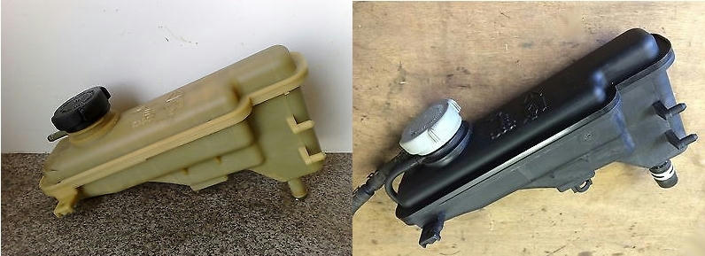 The Pressure Cap Simplistically, it seals the header tank so that the heated coolant will operate under pressure. It thereby allows higher coolant temperatures to be accommodated without loss by evaporation or boiling. A point to emphasise here, is that the pressure rating doesn’t control the engine’s normal running temperature in any way. The pressure rating description (100, 140, 200, etc) is an inheritance from BMW, who calibrated in the French SI system. So, pressure is measured in Pascals (Pa). A Pascal equals one Newton per square metre, a rather small pressure. It’s lower, for example, than that £5 note exerts on a table top. The numbers printed on the caps are kiloPascals (kPa =1000Pa). Helpfully, there's a convenient if approximate relationship between kiloPascals, atmospheres (atm) and pounds per square inch (psi). 100kPa = 1atm = 15psi (approx) 140kPa = 1.4atm = 21psi (approx) 200kPa = 2atm = 30psi (approx) The cap is made from a precision moulded glass reinforced plastic (GRP). The polymer code is PA66-30G, which translates to Polyamide 66 with a 30% glass fibre fill by weight. Polyamide 66 is hexamethylene adipamide, more commonly known as nylon’ (specifically nylon 66, since there are theoretically hundreds of nylon polymers). The cap’s individual components are locked together in a way that prevents dismantling. So, to figure out their secrets you have to pull them apart using hand tools, a Stanley knife, Dremel disc, hammer & chisel or whatever works. This is where we start (photo Google Images). 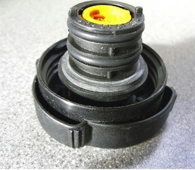 If you're familiar with the pressure cap, you'll know that there are three rubber seals (two o-rings and a flat washer), all fitted on the central body. This housing or cartridge is fastened to the outer cap/hand wheel, but is quite loosely mounted so it turns independently. The end of the cartridge has a yellow plug/insert with the pressure rating (140) indicated on the face (the colour may vary). The insert has a gap around it that's open to tank pressure. If you blow into this gap, the air escapes higher up through a hole in the cartridge. The next photo shows how the cartridge is fastened to the outer cap by four lugs (one is highlighted). These engage around a flange on the cartridge and are shaped so it will snap into position during manufacture. There's no way they'll separate in normal use, even though they're a slack fit. 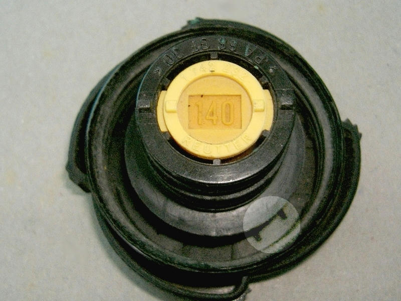 The lugs can be persuaded to release the cartridge if you apply a Stanley knife in the gap and whittle one of them down. You can then extricate the cartridge sideways using brute force. Here's the outer cap/hand wheel with the cartridge removed. This one's from a grey '100' type, but the '140' black type is identical. You can see the retaining lugs, with one cut away. 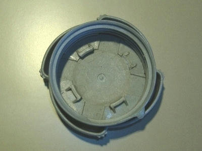 The next photo shows detail of the lugs. You'll see they're designed for one way assembly but are a slack fit on the cartridge. 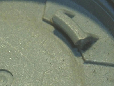 The cartridge will snap into position during manufacture by applying high downward force. The next photo shows the outer cap venting holes around the periphery, above the thread. 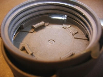 These four holes open into the finger grips, which are hollow and allow excess pressure or ejected coolant to be discharged downwards onto the header tank. One wonders if the earliest caps (used with the black header) didn't have these vents? With the black tanks, ejected coolant was directed to the discharge pipe in the neck. Once you've got the cartridge out, this is what you get (rubber seals are removed). You can see the retaining flange at the top. Notice how the edge is abraded by the lugs when screwing the cap on and off.  In the photo you can see that the lower half of the cartridge is tapered. This ensures a pressure tight fit when it's pressed by the cap into the tapered neck of the header tank. Efficient sealing of the rubber rings doesn’t need very much downward force. The taper action ensures it, but will also cause taper locking if too much pressure is applied. There are reports of this happening when a leaking cap has encouraged the brute force solution. It’s possible to lock the taper so tightly that outer cap is actually snapped-off. Extraction of the cartridge from the header tank may then require even more brute force. In the photo, you can also see the primary valve spring. This controls the release pressure. The valve is located inside the cartridge and the whole assembly is held together with a cross-shaped insert on the flange. This appears to be bonded/welded in position. However it's held, this end piece is impossible to remove without destroying it. The next photo shows what it looks like before you attack it. 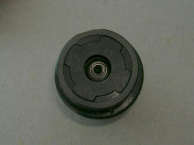 Visible through the hole is a conical hairspring which holds the vacuum relief valve. This allows air to be sucked back into the header tank if any pressure is released when the system’s hot. It's very light and you can blow it open with your mouth. So, won't need more than -1psi or so (vacuum) to open. Without this relief, the radiator could collapse following a boil-over. Before going into the valve housing, it's worth looking at some other features, especially the vent holes. 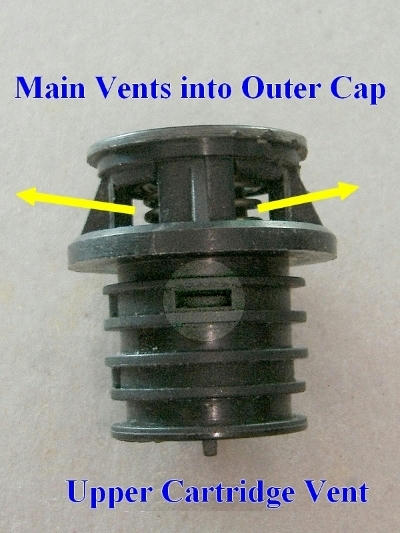 At the very top are the four large vents for the release of over-pressure. Any coolant ejected will come out through these and into the outer cap. Between the upper o-ring and the flat washer is a rectangular vent, highlighted above. This connects with the annular space mentioned earlier. When you blow past the end plug, the air escapes here. On the opposite side, between the two o-rings, is a small hole/drilling. I've labelled it bleed hole.  You'll see the hole is yellow on the inside. This is the inner wall of the '140' end plug. The only way to get the plug out, is to cut the cartridge vertically so you can expand it and pull the plug out using pliers. It's compression-fitted into the cartridge and has two sets of teeth to lock it in place. When you manage to get it out, a thin rubber diaphragm comes with it. 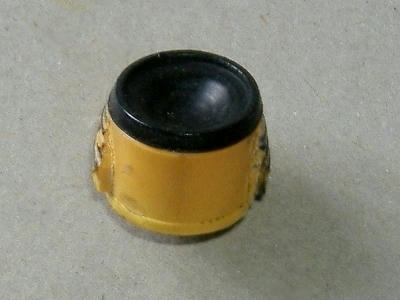 The insert is hollow and is sealed by the diaphragm. The 'chamber' so created is connected to the outside via the inter-ring bleed hole. The next three photos show the chamber, the bonding teeth and the bleed hole. 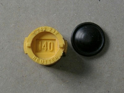  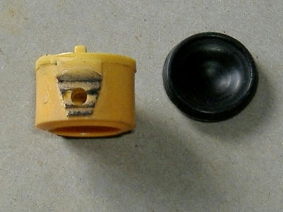 The teeth stand on two raised sections, so when fitted there's the annular space between the plug and the cartridge body. This allows you to blow past it and is the route high coolant pressure takes during a release. An interesting point here is that this bleed hole is absent in the earlier ('100') type cap. The end plug (black or grey in that case) is identical to the 140, except for this hole. It's a bit of a mystery as to why there’s a diaphragm in the ‘100’ cap. Maybe I'll add more about it in due course. To get into the valve housing, I found the easiest way is to slice the top off using a Dremel disc. The four brackets forming the pressure vents and were cut through along the lines shown in red. 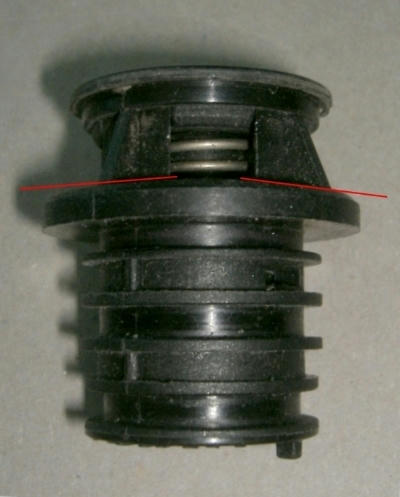 This allows the main spring to relax, so you can remove it and the valve unit from the cartridge. The next photos show the main spring from the 140 and a 100 type for comparison. 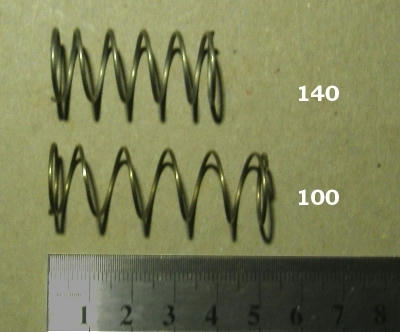 They have different compression rates, so the longer 100 spring is weaker than the thicker 140. With the spring removed, the main pressure valve comes out. It's quite a clever little gizmo with an integral vacuum relief valve.  The white washer is the rubber seal and sits on an annular seat in the cartridge. The plastic body is hollow and contains the vacuum relief valve. This vents atmospheric air downwards, through the lower holes. The narrow domed end of the unit passes through a short guide collar and protrudes slightly with its end siting on the diaphragm. Here's all the components set out in order, with the end piece cut off. 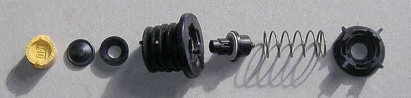 I've combined all this into a sectional drawing which might help explain how it works. 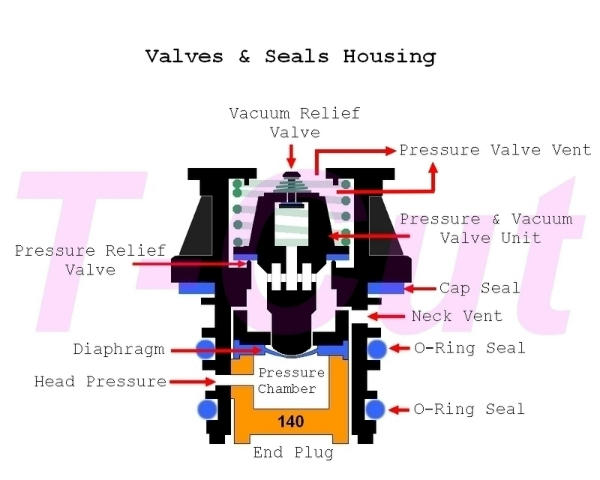 Here, the blue parts are made of rubber. The pressure and vacuum relief springs are green. The drilling between the o-rings into the yellow chamber is labelled ‘head pressure’ for reasons that will be clear when the cap/tank assembly is discussed. Adding the outer 'hand wheel' to this drawing gives the cap assembly. 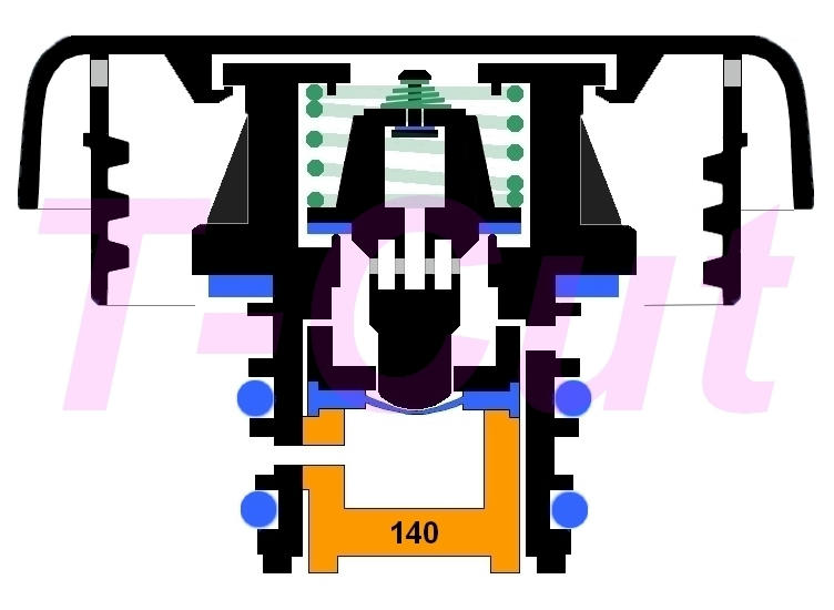 This drawing shows the cap relaxed so it's easier to understand. When it’s screwed down, the o-rings and flat washer are more compressed than shown here and in the later drawing. The underside of the hand wheel presses down on the top of the cartridge. The Header Tank The header provides a small reserve of coolant and permits thermal expansion and pressure control as the engine heats up. It’s located as the highest part of the cooling system, so any circulating air bubbles will be collected through its connection to the cooling circuit. This assists in bleeding air from the system during a refill. The principle is exactly the same as the header tank in a domestic central heating system. The connection to the cooling circuit is by a single, small bore hose from the tank to a T-piece in the bottom radiator hose. It's therefore standing on the return leg to the pump where cooled coolant is cycling to the thermostat on the inlet side of the pump. Obviously, there’s no formal circulation through the header under normal running conditions. The tank is a three part moulded GRP (again PA66-30GF) assembly consisting of the main tank body (lower part) the upper tank section and the filler neck. These are sealed together around the outer edges. The filler neck is threaded externally to accept the pressure cap and incorporates a small bore hose connector. This receives the air bleed hose from the inlet manifold, the cylinder head/heads and the upper radiator. These individual bleed points are Tee'd together before going into the filler neck connector 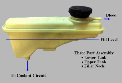 The black tanks have two pipes connected to the filler neck. The second one discharges any ejected coolant downwards behind the radiator. This is shown in the next photo, which I collected from the forum. I can’t remember whose it is, so hope the owner doesn’t mind my using it. The overflow connector opens into the annular space in the neck, so it's a simple gravity drain. In the event of a violent pressure release, this drain is unlikely to cope with a significant volume of coolant. Most of this will discharge via the cap finger grips as per the buff tank. 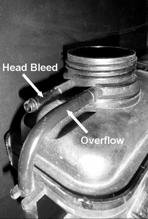 The internal fins/baffles in the header are well known to owners who regularly check the coolant. However, they may not realise how complex the internal structure actually is. It’s difficult to see the interior by looking into the filler neck and even a small endoscope is impossible to position well enough to see everything. This is the best I could manage. These fins run along the top of the tank.  If you shine a light through the buff tank, it’s apparent that it’s divided into three sections by solid walls. To allow coolant to pass through they have a small ‘door’. More on this below. The following graphic shows the general layout of the fins/baffles as perceived externally. Note the three sections. 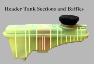 Their presumed function is to reduce sloshing of the contents. The isolated central section may be a vestige of the level sensing system that MGR intended to fit, but never did. This is evident on the earlier tanks, which have a sensor bracket at this point. Photo Google images. 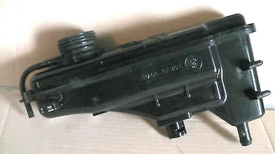 Because the fins are positioned along the full length of both the upper and lower tank, straddling the down pipe, they may also minimise the volume of any ejected coolant. The next few photos show the layout of the fins. I split the top off this one using a hammer and chisel. It looks like the parts are actually ‘glued’ together with a resin bead that squashes around the seam before curing. Here’s some of it I loosened with a knife. 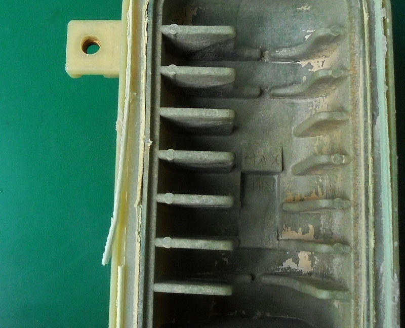 Note the blue staining and pinkish sediment, which is present on all the coolant contact surfaces. The pink crusting seems to be a characteristic of OAT antifreeze and may be caused by calcium hardness in tap water. If so, it certainly shouldn’t happen. I don’t know if this is something the current OAT formulas do, but I don’t think this deposit appears when deionized water is used. 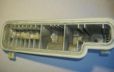 Next is the top half, which shows the blue staining rather better. I suspect this is due to a change of antifreeze from red OAT to a basic blue type. Interesting that the sediment remained pink. 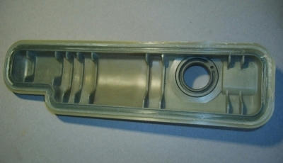 The walled off central section is shown in more detail below. The base here has a circle marked where the ill-fated sensor would have been. Note the two small ‘hatches’. 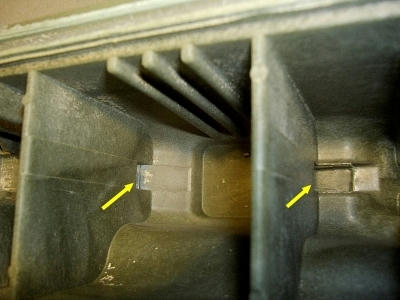 And the all-important Min/Max level indicators (and more pink sediment). 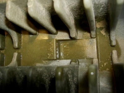 The difference between the Max and Min inventory is about 100ml, so the smallest leak will quickly push the contents to the attention zone. No wonder MGR planned on fitting a sensor! It also explains why refilling the system is quite a slow process. The small doors shown above throttle the flow significantly. This was observed when filling the lower tank section under the tap. Of some importance is the design of the filler neck and the bleed system. The neck has a concentric inner sleeve that's tapered to take the pressure control cartridge on the cap. 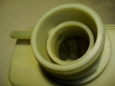 Note the thin raised ridge on the end of the sleeve and the o-ring recesses on the tapered wall. These are where the o-rings are positioned. It’s often assumed that these are wear grooves, but they’re actually moulded into the surface. I guess this may protect the seals from crushing if the cap is over-tightened. Over-tightening is a common error that accelerates the deterioration of all three seals. The taper system doesn’t need much compression to be effective. The bleed hose connector on the outside has a 5mm bore and leads to a much smaller hole in the wall of the inner neck. This is seen in the next image. It’s around 2mm diameter and very prone to blockage. 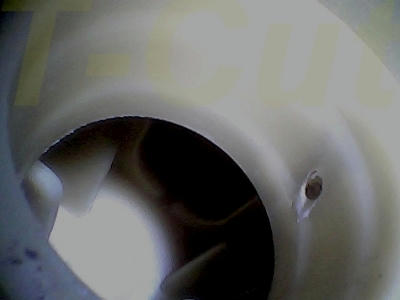 Note the hole is positioned between the o-ring recesses, so this area is sealed top and bottom when the cap’s in position. It's clearly impossible for coolant to pass through here and into the tank under normal running conditions. So, this small hole connects the head bleed to the pressure chamber in the valve cartridge. Another facet is the position and direction of the hole. The above photo shows that it's drilled through the inner neck at an upward angle and so connects with the 5mm passage positioned higher up. This poses an interesting problem. How do you unblock the hole in the neck when it becomes choked with debris? Clearly, you can't use a length of wire or a long drill from the outside. Drilling it through would actually ruin the tank. It has to be cleared using a piece of wire bent at 45 degrees, so you can probe it upwards from within the neck and extract a blockage. Avoid pushing stuff ‘through’ the hole because it won’t go anywhere other than into the bleed pipe. So, if this hole gets blocked, the connected part of the pressure cap’s mechanism won’t work. This begs the question, how can the head bleed operate when the pressure cap's screwed down or indeed if the little hole’s blocked? A closer look at the top half of the tank reveals the answer. Another drilling is present, about 3mm bore and hidden from view. This photo shows the underside of the filler neck. 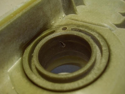  Here, seen from inside the tank, the hole labeled '1' is the small inter-ring drilling and '2' is the true bleed that drains directly into the tank. This hole joins with the 5mm channel at right angles. So what we have is this: Cross Section of Filler Neck 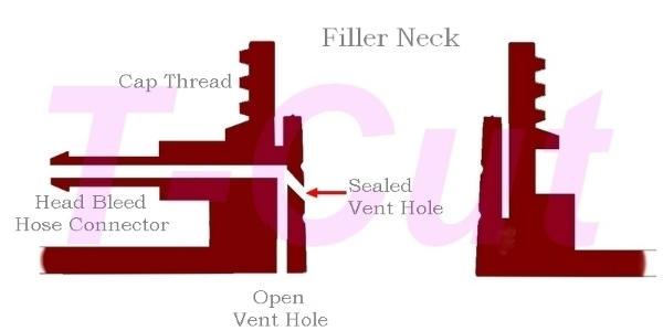 Adding the pressure cap gives the complete assembly. 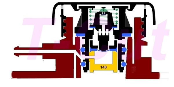 The bleed system automatically vents air from the head, radiator, etc. when refilling with coolant. During this operation the pressure cap is off and the small vent hole is visible in the neck and the large vent out of sight. As the system fills up, displaced air is released via both bleeds. When all the air has been vented, the bleed hoses and the connector pipe remain full of coolant. If the engine is running with the cap off and the pump pressure is high enough, it may transfer coolant into the tank through the bleed holes. This is illustrated in this image taken from a video sequence. It’s a KV6 header with the engine at high revs. 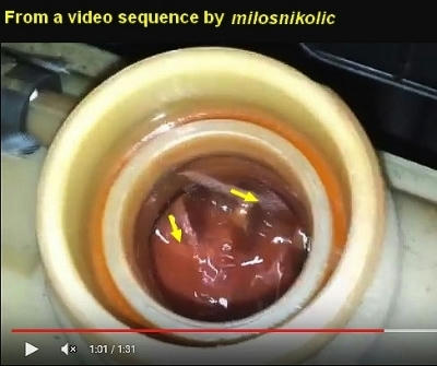 Note the two flows. The primary bleed flows downwards into the tank. The smaller bleed exits sideways. In a normally running engine, I have some doubts that this flow is of any particular significance other than demonstrating that the smaller bleed hole is clear. However, I’ve been unable to replicate it in my 1.8T after refilling and bleeding it according to the MGR Manual. The manual makes no mention of the bleed holes or any flow through them. With the engine running from cold, I’ve observed no flow through either bleed hole during coolant warm-up/expansion nor when revving the hot engine. It begs the question as to what driving force is available to create the high speed flows seen above? There’s a significant pressure drop across the long vent hose and with coolant freely circulating the main system I’m surprised it happens. More discussion perhaps? There are Caps and there are Caps The 140 cap is clearly a dual acting system, so the system pressure acts on the main valve in two ways. There’s the direct route through the annular space around the insert and into the void around the valve. This is a pneumatic pressure, air and water vapour. There’s also the indirect route via the drillings into the pressure chamber and diaphragm, which also acts on the valve. This is essentially the hydraulic pressure in the head, because the bleed route is flooded throughout. Both systems are in equilibrium under normal conditions. It’s clear from the drawing that the o-rings have an equal pressure at top and bottom under normal conditions. In other words, they don’t have to seal the tank pressure, but simply isolate the pressure chamber. It’s the flat rubber washer at the top that alone maintains the running pressure. This washer needs minimal compression because the annular ridge on the inner neck enhances the sealing force (check out the surface of your washer).. This is where many caps are damaged by over-tightening. With a good flat washer, the system should pressurize normally without any o-rings in place. Anyone fancy trying it? The older 100 cap has the same internal construction, but it doesn’t have the pressure chamber connecting hole. The chamber itself is there, as is the diaphragm. So, the second route is blocked and this means it’s a single acting system and doesn't actually need any o-rings. It’s as if the basic cap was produced for two different applications. This proposal is to some extent borne out by a note I found regarding MGR/BMW’s intentions at the time the 140 cap was introduced. The basic 100 cap was fitted to all early petrol models until BMW come into the picture. In some of their own engine’s they had a problem with coolant over-pressure and discharge. This is due to heat soak. Heat Soak When an engine is worked hard, particularly in hot environments, a significant heat reservoir is built up in the head and block. This slowly dissipates after shut down. Without pump circulation, the head contents (a 50% glycol solution) can superheat and boil. This happens at around 110°C at 15psi (or 120°C at 22psi) and so creates enough back pressure in the entire cooling system to force coolant up into the header tank. Some will be ejected and if the pressure exceeds these figures the release would be hazardous.. BMW anticipated this would happen with the turbocharged 1.8 and the diesel. The latter has a high heat capacity cast iron block which would be a bad thing in heat soak situations. The 140 type cap was therefore introduced. One wonders whether MGR’s ‘100’ cap before this point was somewhat different from the 100 used by BMW? I suspect the reason why the ‘current’ 100 and 140 caps are basically the same (except for one hole) is due to Reutter, the cap’s manufacturer. They apparently offered a price incentive if BMW fitted the same design to all the 75/ZT engines. We therefore see caps of different ratings of identical construction except for a single hole. But it raises the question as to why the 100 cap has the o-rings? It should work fine without them. Anyone ?? So How does it Work? This is how I think it works, but if anyone has a deeper insight on this I’ll amend it periodically. In normal running, the header tank is not within the coolant loop and is not affected by the pump other than receiving the tiny bleed. It stands on a stagnant leg located on the lowest section of the pump inlet hose. The tank contents may warm up from the bleed and by thermal conduction up the leg, but should never reach the temperature of the engine. Pump speed should have no effect on the volume of the coolant in the tank. This applies whether the pressure cap is in place or not. Thermal expansion of the coolant is accommodated by the header tank. The surging of coolant level sometimes reported when an engine is revved is abnormal in my opinion. It suggests an increase in total coolant volume or a reduction in the capacity of the hardware. Located on the pump inlet side of the circuit it’s difficult to envision that physical changes in the hoses are the cause. The pump generates around 1-2psi differential across the radiator outlet at 2000 rpm. This was determined experimentally on a PRT removed from a 1.8T system known to relieve at 2000 rpm. I assume all pumps will have a similar displacement/pressure. The effects of engine revving on KV6 header tanks under ‘normal’ and ‘abnormal’ conditions are illustrated in the milosnikolic videos mentioned earlier. A link to these can be provided for anyone interested. As noted earlier, I have doubts about what’s regarded as ‘normal’. Another discussion point. In a heat soak situation, the hydraulic pressure in the head increases dramatically and much faster than the cooling system as a whole. The head bleed thus receives a hydraulic ‘shock’ that must be sufficient to pressurize the sealed chamber and lift the relief valve. This must occur even though the bleed circuit is open-ended to the tank. I guess this pressure initially exceeds the capacity of the bleed. With the main valve opened hydraulically the over-pressure in the head is momentarily relieved by the cap’s main vent. Little or no coolant will be expelled when this happens. Conclusion There’s no doubt that the header tank/pressure cap assembly is surprisingly complex. The drawings I’ve made are accurate translations of the parts I have to hand and there may be a variation not examined. The mechanisms proposed are for discussion and may require changes. If corrections are needed or additional information becomes available, I’ll amend this write up periodically. Disclaimer: You are responsible for any work or modifications carried out on your car and you undertake any such work at your own risk. Neither The 75 and ZT Owners Club nor the original author of these How-To's can be held liable for anything that may happen as a result of you following these How-To's. Any modifications should be reported to your insurance company. Last edited by T-Cut; 21st September 2019 at 10:12.. |

|

|
|
17th August 2017, 12:38
|
#2 |
|
This is my second home
Rover75 and Mreg Corsa. Join Date: Nov 2006
Location: Sumweer onat mote o'dust (Sagin)
Posts: 21,753
Thanks: 341
Thanked 3,660 Times in 2,924 Posts
|
How To Replace the Shannon Tube (Petrol Engines only)
MG ZT owners please note, the v6/190 engine uses 80mm bore tubing. This work was done on a 2004 Connoisseur 1.8 Turbo, but all the petrol engines share the same system for the primary air intake. This guide doesn't apply to the diesel engine. The Shannon Tube is a length of flexible ducting that feeds combustion air into the air filter housing. The tube's inlet is located as high as possible to minimise the possibility of flood water entering the system. The standard location is in the nearside front wing just behind the wheel arch liner. The original Shannon Tube is a spiral wound wire reinforced pipe constructed from cotton weave or similar stuff. Whatever it is, it rots away in a very short time. This is because it gets wet from road spray which gets behind the arch liner and the lower body panel. It's position just behind the headlamp servicing hatch must also make it vulnerable, especially if the hatch is missing. When I went into the space to change a bulb, the Shannon Tube had disintergrated, so I decided to replace it with a more durable version. The pipe/ducting I selected is a wire reinforced 'silicone' type widely available on eBay. You need the 70mm bore version, which can be bought in various lengths. I thought 500mm should be enough and this proved to be the case. There was no need to cut it shorter. It cost around a tenner. Raise the front of the car. I prefer ramps, but if using a trolley jack it's absolutely essential to hold the body safe on two axle stands. Seek further advice on this if you're unsure. You follow this guide at your own risk. Remove the engine under-panel by unscrewing the turnbuckles. Remove the nearside corner panel between the front of the wheel arch liner and the bumper moulding. It's held by five self-tapping screws. For more light, remove the service hatch in the wheel arch liner. It has a single turnbuckle and then requires a brisk pull upwards to free the lower locating lug. Looking up into the space ahead of the wheel arch liner, you'll see the Shannon Tube. Tip When working outside under the wheel arch/wing, it's often difficult to see into the dark places because of the bright sky affecting your vision. If you cover the area with an old sheet held by the bonnet, the resulting tent will improve the seeing no end. Even so, you may still require a torch. Looking into the space, here's what I saw. I'd already removed the other half of the Shannon when I changed the bulb. Image 1 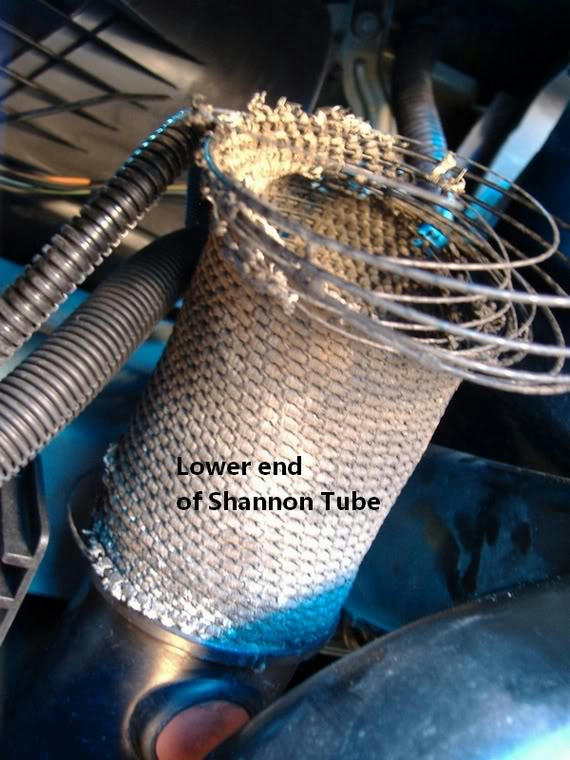 This is the lower end where it joins the plastic ducting from the filter housing. You can see the connection in the next photo. Image 2  The tube simply screws onto the plastic nozzle of the main air duct. You can also see the red rubber drainage valve. After pulling away the remnants of the old tube, this is what I got. Image 3  The fabric simply disintegrated but the soft, plastic coated wire will be come in handy in the garden. Here's the view inside the plastic duct which curves upwards to the filter. The rubber jiggle/poppet valve allows any water getting into the duct to drain out. There may be a small amount of debris in there, which should be removed. Image 4 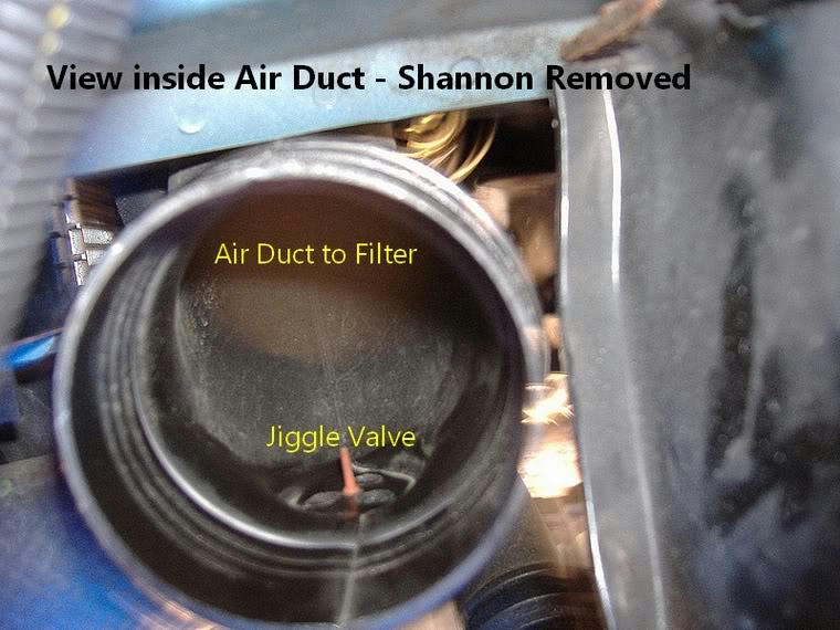 The upper end of the Shannon Tube is terminated with a plastic nozzle/venturi. Here's a photo of the new tube with the venturi fitted. This 'silicone' version is much more rigid than the original. It will bend fine, but doesn't have the slinky flexibility of the old one. The 70mm pipe screws onto the endpiece. It's a tight fit and goes on a lot easier if you apply a squirt of WD40 to the joint. Even so, I held the nozzle in a vice to get it fully home. Image 5  The venturi has a mounting bracket with rubber grommet which locates it on a lug bolted to the bodywork. At the top of the wing space you'll find the mounting bracket screwed to the bodywork. It hangs downward with the mounting lug on the wheel arch side. Image 6  The next step is slightly fiddley. The lower end of the tube has to be screwed onto the plastic air duct. However, it must be orientated so that the venturi mounting grommet is in the correct position and will fit on the mounting lug. It's easy enough to do if you apply WD40 as before and screw the pipe well on and keep testing the position of the grommet. The new tube doesn't have much radial flexibility, so the venturi must be reasonably in line with the lug. The next photo shows the tube fully engaged on the air duct thread. Image 7  And a general view of the attached tube with venturi in position. Image 8 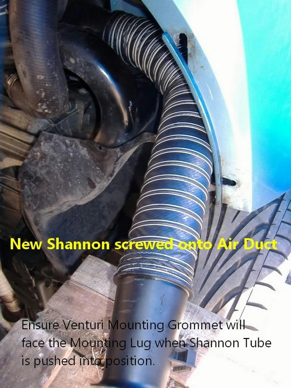 The tube is now bent upwards so the venturi goes right into the top of the wing and the grommet can be slipped onto the mounting lug. The heavy wiring harness may interfere. Here's the venturi just about right. Image 9 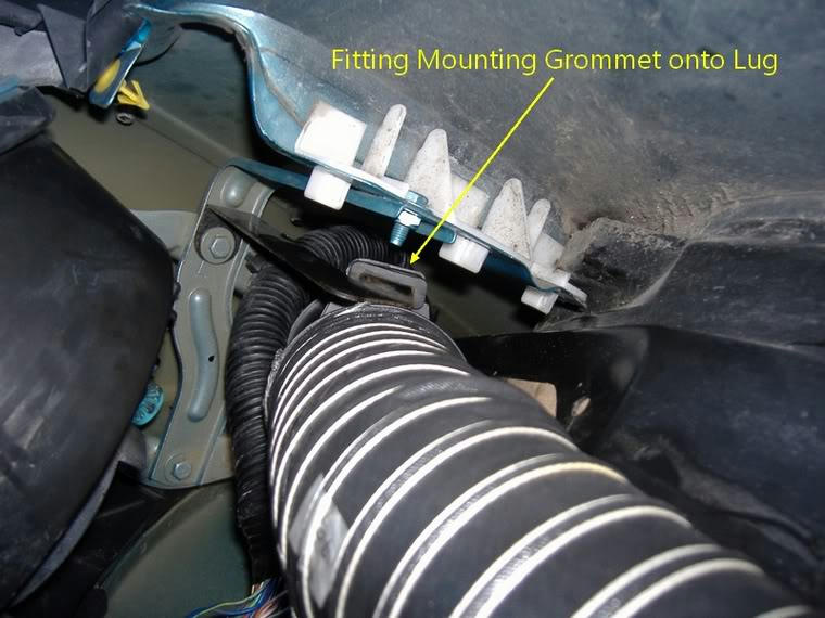 And fully located on the lug. Image 10 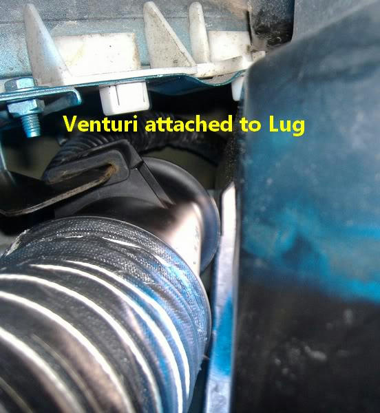 This is what the finished assembly looks like. Image 11  The position of the venturi depends on the orientation of the lug. I had to bend the bracket slightly to improve the refitting, so it stands right behind the inspection hatch as can be seen below. Image 12 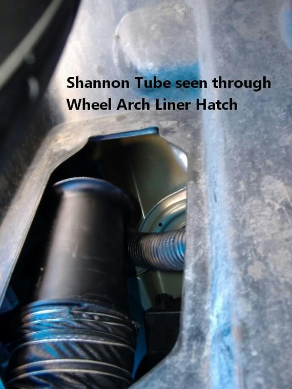 I guess I'll have to detach it again if I have to change the headlamp bulb. Anyway, the neoprene/silicone pipe is water resistant so it should last a long time. Refit the access panels and lower the car. Disclaimer: You are responsible for any work or modifications carried out on your car and you undertake any such work at your own risk. Neither the 75 and ZT Owners Club nor the original authors in this thread can be held liable for anything that may happen as a result of you following this thread's posts. Any modifications should be reported to your insurance company. T-Cut Last edited by T-Cut; 17th August 2017 at 12:44.. |
|
|
|
|
17th August 2017, 12:47
|
#3 |
|
This is my second home
Rover75 and Mreg Corsa. Join Date: Nov 2006
Location: Sumweer onat mote o'dust (Sagin)
Posts: 21,753
Thanks: 341
Thanked 3,660 Times in 2,924 Posts
|
How To Remove the Rear Seat Cushion the Easy Way
Revision dated 2017This is really a supplement to the existing How To, which some people may find difficult to do single-handed. We don't always have Haynes' ever present assistant to help with jobs like this, so after struggling alone and expending much physical effort, I thought I'd show you how I did it the second time around. The rear seat cushion is retained at two points on the front edge and two at the rear. The front fasteners are simple push-in clips, the rear ones are a hook and eye system. This is one of the front floor fasteners that clips into the front edge of the cushion. 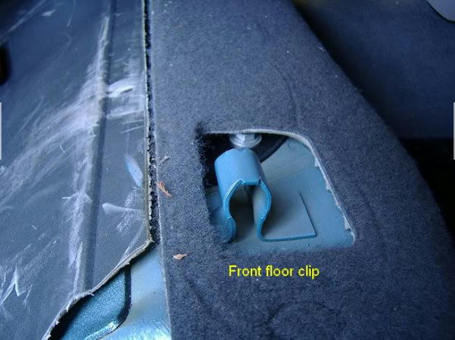 And this is the floor 'hook' that engages the 'eye' on the rear edge of the cushion.  Notice the damage to the sound insulation. This is caused by using the brute force method and which is avoided here. This underside view shows the front spring 'latch' and rear 'eye' made from heavy spring wire.  To release the front edge, stand outside the rear door, grab the front edge of the seat cushion and pull it smartly upwards. The latch/clip will release. Repeat on other side. You can now lift the front edge of the cushion to see underneath. Notice the hooks and eyes engaged at the rear edge. As usully recommended, pushing the whole cushion backwards to unhook it can be difficult. This is because the wire 'eye' piece is kinked (above image), making the effort very inefficient. Also, getting your hand into the rear of the seat while pushing on the cushion can be difficult and also damages the floor pad (ref. earlier images) So, to release the wire 'eye' a long tool of some sort would do a much better job. For my second go, I used a long screwdriver to push the eye backwards off the floor hook. You can lift the cushion just enough to see what you're doing, but it's still frustrating because it slips off the wire. A much better tool is about two feet of old broom handle. I trimmed the end with a hacksaw to give a nicely fitting socket.  Place this under the seat and engage the 'eye' wire.  A simple rearward push on the tool while lifting the end of the cushion releases the fastening. Repeat at other side and the cushion can be lifted off the floor. 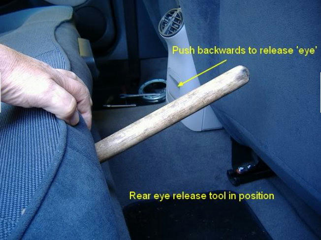 Refitting is basically the reverse of all this. TC Disclaimer:You are responsible for any work or modifications carried out on your car and you undertake any such work at your own risk. Neither the 75 and ZT Owners Club nor the original authors in this thread can be held liable for anything that may happen as a result of you following this thread's posts. Any modifications should be reported to your insurance company. |
|
|
|
|
17th August 2017, 12:53
|
#4 |
|
This is my second home
Rover75 and Mreg Corsa. Join Date: Nov 2006
Location: Sumweer onat mote o'dust (Sagin)
Posts: 21,753
Thanks: 341
Thanked 3,660 Times in 2,924 Posts
|
How To Understand Fuel Tanks
This is my revision dated 16 July 2017 This is another bit of work in progress and there are probably things I've got wrong. Hopefully these will be corrected through informed comment. I'll edit it as additional info is gathered and mistakes are corrected. Over the years, Ive read loads about what happens in the fuel tank if for example, a diesel pump fails, or Fuel Filter Syndrome (FFS) develops in a petrol system. Thankfully there are only a few different problems, but they do happen frequently and they get discussed a lot. However, Ive often felt the explanation of cause and effect is little more than guesswork or misinterpretation. So, I decided to learn what I could about the way tanks work and did some research. I admit I was surprised. Boiling it down, I thought a simple fluid flow diagram for the fuel tanks would be useful. Basically, if you understand the flow paths you can explain the things that happen. What surprised me is the fact that all fuel tanks contain not one, but three pumps. In addition to the electric pump located in the RHS of the tank, there are two static pumps located deep inside the plumbing system. These transfer fuel within the tank and ensure the electric pump inlet is always submerged, no matter what the fuel inventory or the driving conditions. Now this seems contrary to many things Ive read on the forums, especially regarding diesels. The quarter tank rule for diesels has always intrigued me and I now see the explanation of it. Similarly, the idea that under certain circumstances the RHS of the tank will have all its contents transferred into the LHS seems an illogical design feature. So I made some drawings of the petrol and diesel tanks to simplify the workings. 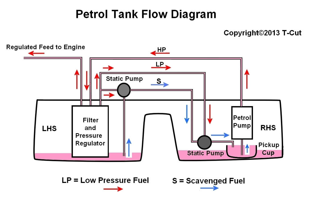 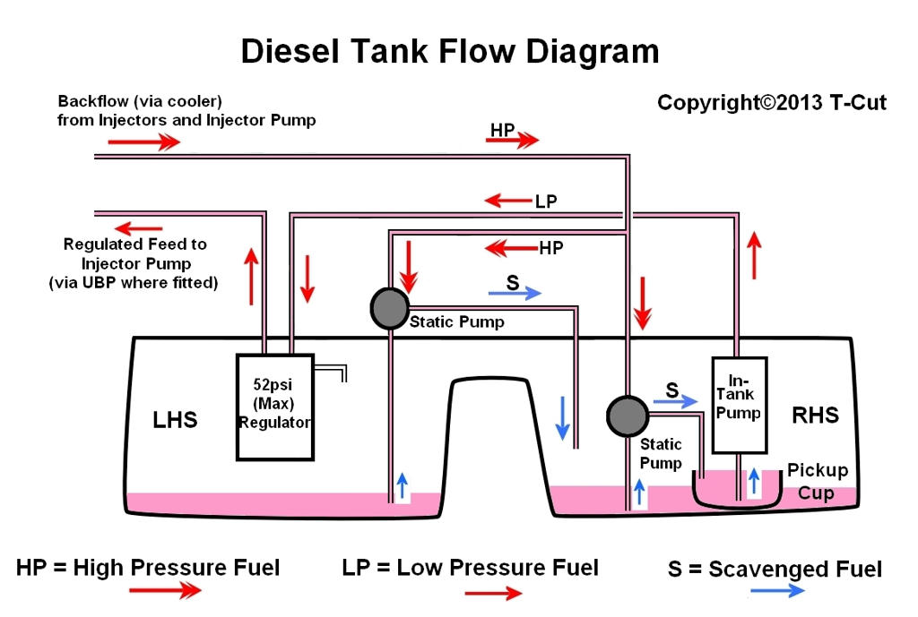 These show only the liquid flows. Vapour and pressure handling are omitted. The saddle tank and interior pipework are shown diagrammatically, so all this stuff is a bit different in reality. The idea behind the internal plumbing becomes apparent when the fuel level is below the central dividing hump. It makes most sense when the fuel inventory is very low, so the drawings show that situation. Diesel or petrol, the system is identical in principle, but the way its done is slightly different. The primary electric pump, whether diesel or petrol, is a centrifugal (impellor)type. The diesel one generates around 30psi at the outlet when in top condition. The single petrol pump generates around 50psi. The UBP in the diesel is a positive displacement type with a 'pigtail' gear design. A centrifugal pump can run against a closed outlet while maintaining its delivery pressure, but it must be adequately primed. To ensure this, the pump is fed from a permanently flooded pickup or swirl cup. Its the job of those other two pumps to keep the swirl cup full. When there's plenty of fuel in the tank, the electric pump and its swirl cup are completely submerged, so while there are transfers happening within the tank, they only become important when the inventory falls. At very low inventory, any air getting into the pump inlet is vented off at the upper end of the pump through a scavenger/priming valve which closes when the pump is hydraulically locked. Make note of this valve. The two secondary in-tank pumps are static inductors based on the Venturi principle. These get their motive power from pressurised fuel generated by the electric pump (petrol) or the diesels HP injector pump back-flow from the engine. Their sole purpose is to ensure the swirl cup remains full under all conditions. Since they will only work when pressurised fuel is fed into them, any circumstance which reduces this pressure will cause a tank malfunction. For example, the diesel HP backflow passes through the cooler mounted externally near the tank. A fuel leak from the cooler may inhibit delivery from the inductors. Similarly, FFS in the petrol tank may inhibit feed to the inductors. This will also cause tank malfunction and explains why FFS is sometimes accompanied by an absence of fuel in the RHS. Diesels with two electric pumps (ITP and UBP) may under certain conditions fail to get sufficient fuel if one fails. The ITP has adequate delivery capacity when assisted by the UBP. So, when it has to work alone, it needs to do the work of the UBP as well. Whether it copes with the load depends very much on the lift it has to cope with. The lift of a pump is determined by the outlet pressure. The required lift is the vertical height between the fuel surface in the tank and the HP pump inlet on the engine. While the height remains below some critical point, fuel will get to the engine. The only variable in this equation is the fuel level. As the level drops, the required lift increases, until a point is reached where delivery fails. I assume this is at the nominal quarter tank level. As fuel delivery reduces, the volume of HP backflow from the engine will fall. This backflow is vital for the correct handling of fuel by the Venturi pumps. As noted, these scavenge fuel from the left side of the tank into the right and from there into the ITP swirl cup. Clearly, if the scavenger pumps are inoperable due to lack of HP backflow, the RH side of the tank will run dry. If the ITP fails before the UBP, this has to lift fuel from the tank and deliver it to the HP pump on the engine. I would guess then, that the UBP is a different type from the ITP and is logically positive displacement. (This has subsequently been confirmed and there are some nice photos (somewhere) of the interlocking spiral worm gears). It must have sufficient 'suction' to raise fuel from the tank (via the dead ITP) on startup. It would be interesting therefore to compare the innards of each. Again, the quarter tank rule seems to apply, so that the UBP can cope with the lift and engine requirements. As the UBP eventually fails, the scavenger pumps fail and fuel seemingly becomes transferred the LHS of the tank. Later diesels only have a single primary pump (ITP). This is a higher spec'd type with the lift and capacity to cope with the demands of both the engine and the tank scavenging system. If this pump ever begins failing, you'd expect the outcome in terms of fuel distribution to follow a similar pattern. Disclaimer: You are responsible for any work or modifications carried out on your car and you undertake any such work at your own risk. Neither the 75 and ZT Owners Club nor the original authors in this thread can be held liable for anything that may happen as a result of you following this thread's posts. Any modifications should be reported to your insurance company. TC |
|
|
|
|
19th August 2017, 09:26
|
#5 |
|
This is my second home
Rover75 and Mreg Corsa. Join Date: Nov 2006
Location: Sumweer onat mote o'dust (Sagin)
Posts: 21,753
Thanks: 341
Thanked 3,660 Times in 2,924 Posts
|
How To Vacuum Refill the Coolant
Ethylene glycol, the main ingredient of OAT antifreeze, is toxic by ingestion. Needless to say, do not allow children or animals nearby when you are handling used or new coolant or OAT antifreeze concentrate. Old coolant should be flushed down the domestic drain using plenty of water to dilute it. This only applies to domestic quantities from a single engine. Commercial garages must comply with the relevant regulations on antifreeze disposal. The OAT coolant should be replaced every 60K miles or four years according to the MGR service schedules. As most members will know, the 'official' method for filling the system is by vacuum. This method completely eliminates air locks and bubbles because there's no air in the engine, radiator, heater matrix or pipework to become trapped. It's the ideal way of replacing the coolant when its service life has expired. Unfortunately, vacuum filling is generally regarded as a 'commercial' operation, done only by garages having specialised equipment (MGR Tool 26R002 or an equivalent such as the Sealey VS004, etc.). Of course there are other ways of doing it. Here's mine. The crucial thing is the vacuum. The commercial tools evacuate the cooling system using an ejector pump powered by compressed air. There are no moving parts to this, so it's pretty neat, but you do require a whacking great compressor. Thankfully, a Pela oil pump (or the Sealey version) produces a good vacuum, so if you've bought one for doing your oil changes, this is another job it will do. The second important thing is to connect the Pela to the cooling system so it's airtight. This is where the rubber bung comes in. It fits into the coolant filler neck in exactly the same way as the commercial rigs. Let's take a look at the header tank neck. Image 1  You need a soft, natural rubber bung to fit in here. That's a pretty big bung of the type sold by lab suppliers. The ideal size would be one with the small end 42-43mm diameter, so it fits tightly in the neck. Unfortunately, I couldn't find one on eBay, so I bought the nearest available. This is about 45mm across the wide end so it fits in the neck upside down. Usefully, the raised annulus inside the neck provides a good seal on the flat face of the bung. To adapt it for use, the bung needs a single central hole. This can be 3/16" - 1/4" in diameter to take a pipe connection. You can buy bungs pre-bored but mine wasn't, so I had to do it myself. You can buy cork/bung borers from eBay as well. Luckily, I had one from my lab days and found it quite easy to cut through the rubber. You can make a cork borer from a short length of metal tubing. It must be thin walled and about the same OD as the required hole. The outer edge of one end should be sharpened using a fine file or grindstone. You really need a handle on it so you can turn it back and forth as you cut into the bung. Maybe bend the opposite end to give some purchase or a pair of pliers, etc. would do to hold it. Lubricate the cutter with water or spit and it will sail through. Watch your hand as the blade emerges! To connect the vacuum pipe and the coolant feed pipe, you require a T-piece connector. I found a nice brass one on eBay, but the plastic ones sold by lab suppliers will do fine. All this stuff can be found on eBay. Here's the way it connects. Image 2 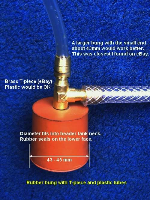 As you can see, mine is upside down, but that doesn't matter as long as it seals in the neck when held down. The plastic tubing can be the plain 1/4" bore polythene type. You don't need anything fancy. The braided tubing is all I could find to connect the Pela hose to the bung. The important thing is that all the joints and pipe connections are airtight. When you use this rig, one or both pipes are clamped off at some stage. The best way to do this is bend the tube together and clamp it. It just needs holding together firmly, squashing it isn't necessary. Two sets of Mole grips are ideal. When you clamp the coolant feed tube, leave enough pipe on the open side of the clamp to submerge in the feed bottle. I used a 5 litre bottle of 50% OAT solution, with another litre or two to top up with. Your quantity will vary. Here's the set up. Image 3  If you have the manually controlled heating system, turn it to maximum heat and leave it there throughout the refill operation. Drain down the cooling system completely as described in the Haynes manual. Ensure you get as much of the old coolant out as possible. The Pela reservoir is useful for measuring it if you manage to catch it all in a bucket (not easy). The photos used here show a 1.8 Turbo model but the vacuum filling process is the same for all models. After draining down, reconnect all the hose connections, etc. you removed earlier. It's also a good idea to replace some of those spring type clips with Jubilees. This is especially worth doing for the awkward to reach ones. If you want to do a clean water flush, do it before the final reconnections are made. Here's where it gets interesting. Image 4: The bung in position.  The pipe going to the coolant supply bottle should be clamped to start with. The pipe to the Pela is not clamped. Here's another shot of the set up. Image 5  At this stage, I'm ready to evacuate the system. The coolant bottle isn't needed just yet, so it's still sealed. If the bung is a slack fit in the neck, you'll need three pairs of hands to start the vacuum. Once there's a slight vacuum in the system, the bung will automatically hold down. Begin pumping the Pela until the bung is self-sealing and you don't have to hold everything together. Keep evacuating until the Pela requires some effort to pull up the pump. As the air pressure in the cooling system falls, the larger bore hoses will collapse. This is a good sign. Here's a photo of mine just before the refill. Image 6 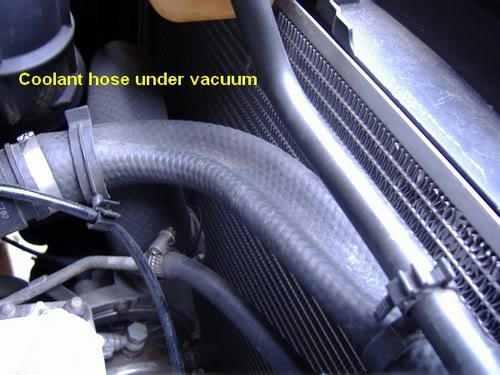 Image 7  When the hoses are fully collapsed, stop pumping and let it stand. You will soon know if there's an air leak because the hoses will re-inflate. If everything's air tight, the flattened hoses won't change over time. They should stay like this for 10 minutes or more. I guess the ideal way is to fit a vacuum gauge to the bung so you can see any leaks raising the pressure (the commercial kits have a gauge). When pumped hard down, this set up will create as good a vacuum as the commercial kit, but you really don't need a vacuum like outer space - the Pela does fine. Fix any leaks before going to the refill step. When you're happy with the vacuum, kink over the plastic pipe to the Pela and clamp it off. This prevents coolant from being sucked into the pump reservoir. The open end of the clamped-off coolant pipe should now be submerged in the fresh supply bottle. This is why you must leave enough open pipe before clamping it off. The end must be submerged in coolant before removing the clamp. Here's the set up. Image 8 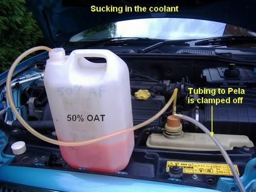 As soon as the clamp's removed, the coolant is sucked pretty quickly into the header tank and will immediately settle at the lowest point of the system. It will progressively fill upwards, going into very nook and cranny as the level rises within the engine. The heater pipes and matrix will fill with no air locking whatsoever. The important thing is to ensure no external air gets sucked in as the feed bottle empties. It's a good idea to top up the bottle before it gets too low, so the complete charge goes in as one lot. If air does get in, you'll have to repeat the evacuation procedure. As the system fills the internal pressure rises a little bit due to the reducing volume, but it should suck in a complete charge. If for some reason you lose vacuum, clamp off the feed tube, un-clamp the Pela tube and re-pump it down again. Now repeat the refilling routine. If you have to re-pump the system when it's nearly full, you must be careful not to lose coolant into the pump line. This can happen when the hoses collapse again, squeezing out the liquid. With care, you won't lose very much. When the recharge is complete, it will return more or less to normal pressure. If necessary, let air in via the feed tube, so you can lift out the bung. The header tank may be full to the very top. If so, use the Pela or a syringe to suck excess coolant out and reduce the level to the standard cold MAX mark at the base of the fins. Replace the pressure cap, start the engine and double check for leaks. If you maintained a good vacuum, there shouldn't be any. The heater should blow hot as soon as the system is warmed up. Refit any other bits removed for the drain down (engine under panel, etc.) Double check the coolant level after a few miles to ensure everything's nominal. So that's it. No bleeding, no squeezing, no air locks. Removing Exising Air Locks Air locks are a common problem with these engines and the bleeding and squeezing routine may not be successful in eliminating them. If you have a persistant air lock that won’t respond to Mr Haynes’ advice, try evacuating the system using this kit. By reducing the internal pressure, any air bubbles in there will expand dramatically. This may be sufficient for them to escape their trap and be expelled through the header tank. If you try this method, be aware of potential loss of coolant noted in the HowTo. As the pipework collapses, it may force some coolant out through the neck of the tank. This can either be caught in the Pela and reused or simply replaced with fresh. When I was looking around for the parts for this kit, I wanted to use valves in the lines instead of clamping them. However, the most suitable valves are pretty expensive so I didn't bother. Same with the pressure gauge idea. You can incorporate all these refinements if you wish, but the general idea is not to spend anything like the price of the Sealey, etc. Disclaimer: You are responsible for any work or modifications carried out on your car and you undertake any such work at your own risk. Neither The 75 and ZT Owners Club nor the original author of these How-To's can be held liable for anything that may happen as a result of you following these How-To's. Any modifications should be reported to your insurance company. T Cut Last edited by T-Cut; 21st September 2019 at 10:16.. |
|
|
|
|
19th August 2017, 09:38
|
#6 |
|
This is my second home
Rover75 and Mreg Corsa. Join Date: Nov 2006
Location: Sumweer onat mote o'dust (Sagin)
Posts: 21,753
Thanks: 341
Thanked 3,660 Times in 2,924 Posts
|
How To fit Access Hatches for the Rear Lights (Post-Project Drive Saloons)
Anyone with a post-2001 model will know what a chore it is to change a bulb in a rear lights cluster. Thanks to Project Drive, the access hatches in the rear end of the boot liners were deleted. This means you have to detach the rear end of the liner to get at the bulb holders.The earlier models have a removable cover in grey ABS plastic which clips over a hatch in the liner. This obviously makes bulb replacement a whole lot easier. Having bought some MG7 style lamps with partial LED illumination, I thought I'd do a proper job by doing this access hatch mod as well. I think being able to get at the new cluster quickly will make it easier to experiment on a full LED conversion. The plastic covers are frequently offered on eBay and can be obtained from 75/ZT dismantlers. I can't find the Part Numbers on Rimmer's site but you need a LH and RH one and can expect to pay anything from a fiver a pair to a tenner each second hand. The first thing to do is remove the boot wall liners. This is described in the Haynes manual, but it's pretty obvious when you examine the boot. Each liner is released by pulling away a section of the lid's rubber sealing strip and removing two push-in type panel fasteners. One is at the rear end and one at the front edge just behind the rear seat frame. They are different types. The rear one is a two piece system, which uses a central pin to spread the holding wings behind the liner/metalwork. These images are linked from the Rimmer site. 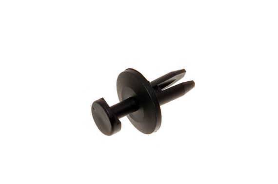 Pull the pin out with pliers and the whole thing will come out. The front end is held by a large fir tree type clip. 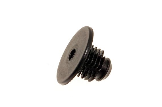 This one is best removed using a clip levering tool because it's difficult to get at. With the two clips removed, the liner can be jiggled free. Haynes tells you to remove the rear plastic moulding that covers the boot latch, but I found this unnecessary. The ends of the liners are retained by the moulding, but this can be lifted enough so the liner comes out. The liners are partly stressed into position, so care is needed to avoid creasing the material as you pull them free. They're are made from a compressed/bonded fibrous stuff which can be cut with a sharp Stanley knife or stout scissors. Here's a pair of hatch covers I got from eBay:  You'll notice there are two flat lugs along one edge and there's a latch sort of fastener on the opposite edge.  The lugs go inside/behind the liner on the inner edge of the access hole. I've not seen how MGR did the fitment for these. I guess there may be two narrow slots punched through the liner to take the lugs. Having access to only a Stanley knife, I just did it my way. The springy releasing clip/latch holds onto the opposite edge of the hole so the cover stays put. It's not particularly elegant but it works if you take care with the cutting. Luckily, the outline of the original hatch cutout is present on the liners, so it's an easy job to cut out the appropriate bit and create the access. Here's a photo of the LH liner. 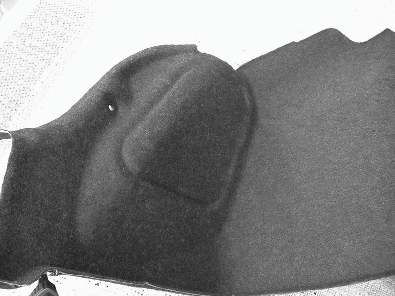 You can see a distinct ridge where the hatch in the earlier liner was located. Placing the plastic panel over this allows you to see where the hole should be. It should be about a quarter inch or so smaller all round than the cover panel. You need a small overlap so it fits properly and looks good. I've marked this cutting line on the next photo.  Using the Stanley knife, carefully cut the liner along the indicated line. It's pretty easy if the blade is sharp. This is what you get.  The next thing is to make some recesses in the edge of the cutout to accomodate the retaining lugs and the latch. This is best done by sticking some wide masking tape along the rear edges so you can mark out the positions and width of the lugs. Position the plastic cover over the hole so it sits properly all round. Pencil in the cutting points for the lugs. Similarly, mark out the position of the latch. There's just a short 'mouth' which holds the edge of the liner.  The depth of these cutouts is made by trial and error. You have to keep testing the fit of the cover bit by bit so you don't overdo it and spoil the result. Don't cut the latch side until you're happy with the lugs. Next, progressively make a cutout to accomodate the latch as shown below. Test the fit of the latch every time you make it deeper.  When you're happy with the fitting, remove the masking tape and it should look like this.  I noticed that the fibre material along the edges of the cutout was slightly loose and would probably fray in time. To fix this, I decided to treat the edge area with a water based PVA resin to bond the fibres and stiffen the cutout. It was actually the stuff used to overlap vinyl wallpaper. Anything similar will do. I painted the PVA along the cutout on the rear side and allowed some to soak into the exposed edges. The liners were then set aside for a day to dry.  When the PVA had dried, the holes were much more stable and tough. I smoothed the edge by lightly sandpapering it. You get enough nicks and scratches fitting headlamp bulbs! Here's a cover in its final position.  The latches on my covers seemed slightly too slack. The springy bit with the mouth seemed to be slightly too far back to pull the panel onto the liner. This may be due to fatigue after too much pressing and fiddling by the previous owner, so I decided remedy it. Using a cigarette lighter, I carefully heated the base of the latch so I could re-position it to sit slightly forward from the liner. It worked very well, but only try it if you're confident. Soften the ABS too much and it's disaster. The liners were then refitted into the boot sides and the covers attached. Disclaimer: You are responsible for any work or modifications carried out on your car and you undertake any such work at your own risk. Neither The 75 and ZT Owners Club nor the original author of these How-To's can be held liable for anything that may happen as a result of you following these How-To's. Any modifications should be reported to your insurance company. TC |
|
|
|
|
19th August 2017, 09:41
|
#7 |
|
Gets stuck in
Rover 75 Saloon Join Date: Jul 2012
Location: Ballarat
Posts: 937
Thanks: 576
Thanked 114 Times in 99 Posts
|
Ah T Cut.
You are a gentleman, a natural teacher and a treasure 
__________________
Love my 75 and it loves me Membership Number 1703 This vehicle was the 82,624th 75 to run off the production line, out of 112,381 This vehicle was the 6,161st 75 2.5 V6 Contemporary to be made out of 8,214 This vehicle was the 9,755th 75 in White Gold Metallic (code: GMN) to be made out of 12,251 White Gold Metallic 75s |
|
|
|
|
22nd January 2023, 18:47
|
#8 |
|
Regular poster
Rover 75 Saloon Join Date: Apr 2016
Location: Folkestone
Posts: 34
Thanks: 0
Thanked 0 Times in 0 Posts
|
Having read the detailed contributions from way back in 2017 etc about this topic I have had this problem surface again recently and have enjoyed piece of mind with my last repair due to the cap breaking down header tank leaking coolant. I traced the leak of coolant in the "V" to an O ring having gone flat/square resulting in coolant spraying out over the V area, I fitted a replacement 140 cap along with fitting the Vitol "O" rings upgraded from the standard Nitol and packing the rings with Silicone grease which appears to have had the desired effect. I now have complete piece of mind with any overheating/ coolant in the "V" of the engine. I also had an issue with the replacement thermostat housing pipes in that the replacement units from Rimmers' were a shorter length than the ones fitted by Lates 600 supplied by DMGRS some 21 months ago ( I have no problems with parts from DMGRS and all work carried out by Lates gave me piece of mind as since then I have enjoyed driving my car as I imagine it should be driven. I addressed the issue with Rimmers' who advised me that the units supplied to me were the standard units which obviously were the standard fit and there were no alternate lengths available which I fully appreciate and understand. No problem, the previously fitted pipes were put back in situ' with replacement "O" rings as the fitted rings had gone flat/square and praise be to the Rover gods all ended well with 100% success. Perseverance paid off. Proves you never stop learning !!
|
|
|
|
|
22nd January 2023, 19:29
|
#9 |
|
Avid contributor
Rover 75 Saloon Connoisseur SE 2.5V6 Join Date: Oct 2011
Location: Aberdeen
Posts: 226
Thanks: 56
Thanked 12 Times in 11 Posts
|
Great pictures and great explanations. Thanks so much for going to the trouble.
 |
|
|
|
 |
|
|


 Linear Mode

