
|
|
|
|
|
|
||
|
|
||
 5th April 2013, 21:32
|
#1 |
|
This is my second home
Rover75 and Mreg Corsa. Join Date: Nov 2006
Location: Sumweer onat mote o'dust (Sagin)
Posts: 21,752
Thanks: 341
Thanked 3,660 Times in 2,924 Posts
|
How To Install Puddle Lights (non-Sunroof Models)
This write-up describes fitting puddle lights to all four doors. The lights have the projected MG/Rover logo and supplied by Radioguy via the Club Forum. Before doing anything, I couldn't wait to see what the logo projection looked like. I connected each puddle light to a 12v supply and was pleasently surprised by the brightness and vividness of the image. I bought the Mk2 Rover logo ($12 extra for some reason). Out of the four I bought, one gave a blurred image on a white screen about 18" away. The lamps should be in focus, but this one wasn't. After hours of investigation, I corrected the problem. I will add more on this if required. For a door lock/BCU-switched power supply, I decided the main courtesy light was the most convenient. I preferred to tap my four supply wires into that and radiate them outwards through the roof space towards the A and B posts on each side. This provides a way of doing it with minimal dismantling. Of course, it's not the only way since the equivalent supply is available elsewhere. The Haynes manual is useful for details on removing interior panels. References here to the door 'conduit' means the concertina type rubber ducting joing the door edge to the door jamb. The door wiring harness passes through this and is the route your new wiring has to follow. Each end of the conduit forms a grommet which can be pulled out by hand from its mounting hole. A small screwdriver is useful for getting it started. I recommend installing and testing one puddle light at a time. Make sure it works properly before starting on the next one. Having all four doors open and stripped of their cards may have practical issues and logistical problems if you need the car to be readily available. 1. Disconnect the battery to avoid shorting anything while wiring up the lights. Take any necessary precautions with this according to your fitted accessories like satnav, radio code, etc. 2. The courtesy light lens should be levered off using a small screwdriver. To avoid fracturing the clips, there's a levering recess as indicated here. 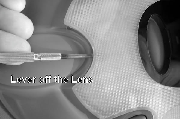 3. The light unit chassis can now be freed from the roof brackets by removing the two large self-tappers. With the chassis released, you can now disconnect the wiring plug hidden above the roof lining. 4. With the courtesy light on the bench, I soldered four male spade connectors onto the switched supply busbar. Ensure to select the correct one as shown the next photo. The spades I used were the 2.8mm crimp type (code red) suitable for 1mm wire. I removed the red plastic crimp sleeve by heating and pulling it off. I then flattened/filed the metal stub so it's easier to position and solder onto the busbar.  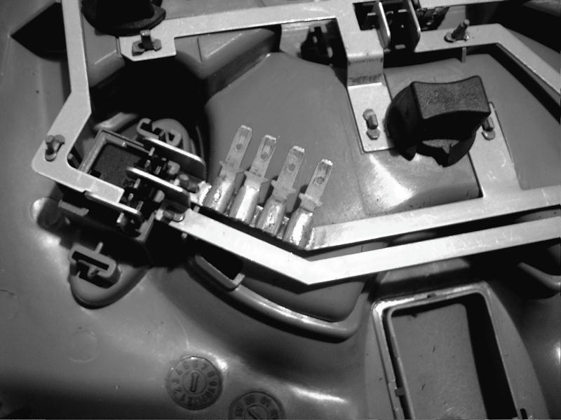 5. I decided to use 1.5 amp (1mm approx) insulated wire in white to feed the supply to each puddle light. You can estimate the length required for front and rear doors by following a route in straight lines from the courtesy light, across the headlining to the top of the A or B posts, down the post to the door conduit, through the rubber conduit into the door cavity and across the door cavity to the puddle light location. The light will be located on the bottom edge of the door card. Now add half as much again for comfort and cut the wires to length. 6. Crimp or preferably solder a female spade connector to one end of the four wires. Protect/insulate the joins with heat shrink as appropriate. 7. You now need a few feet of maleable steel wire about 2mm thick to use as a pull-through for the supply wires. You can get suitable wire from DIY stores or Screwfix. Using pliers, make a small loop on one end. The looped end will be pushed into the roof space (the gap between the headlining and the roof) from the point where the A or B posts start. 8. To access the roof space, pull away the rubber weatherseal on the body door opening down the post. At the top corner, this reveals a small gap above the headlining into the roof space. You can push the probe into this towards the courtesy light hole. When you use the right sort of wire, it's dead easy to do. Push/jiggle it until the loop end is visible.  9.The loop end is pulled through a few inches so you can attach the plain end of your supply wire. 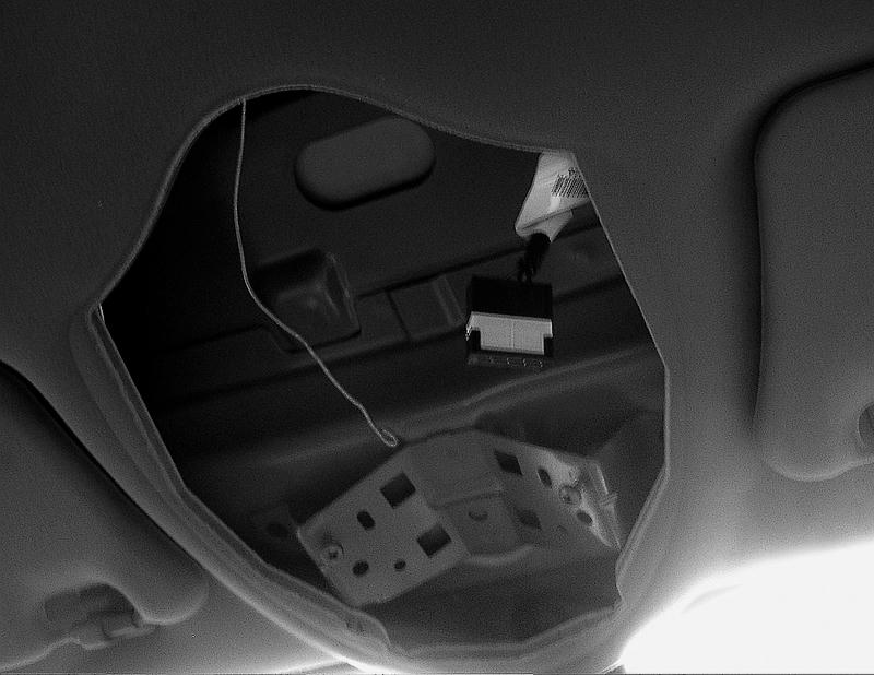 10. Use the pull-through to draw the supply wire across the roof space so it emerges at the top corner of the A or B post. Make sure you don't lose the other end into the roof. You could plug in the courtesy light chassis as support and attach the puddle wire to one of the spade connectors. Detach the wire from the pull-through. To avoid any confusion as the wires are assembled, it's a good idea to stick a label around each one in turn to identify which light it goes to (LHF, RHF, LHR, RHR). 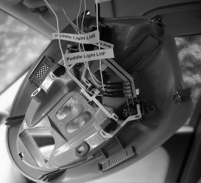 11. The next job is to winkle each wire from the top of the A/B post to the point where the harness cables from the door come through the rubber conduit. The A and B posts house the safety system air bags tightly folded along their length. You must be careful when bringing down your wires that they do not foul these bags in any way. 12. To get the A post wires down, pull away the weatherseal from top to bottom. Remove the plastic panels on the side of the foot wells. Now maneuvre your pull-through wire upwards from the footwell into the dash side so the looped end emerges from the gap in the A post near the dash. Attach the supply wire and pull it down so it emerges in the footwell. Using your fingers, carefully push the supply wire into the gap between the post and the air bag. The wire should be behind or at the side. It shouldn't run along the face of the air bag so it can inflate properly if it's ever needed. All this can be done without removing the finisher panel running down the post. MGR say these panels should be renewed if they're removed. Haynes describes removal/refitting if necessary. 13. On the footwell wall is a large oval grommet that conveys the harness from the conduit in the door jamb. This grommet must be pulled out from the wall. There's a cavity behind it through which you should be able feel the grommeted end of the conduit. 14. With the large oval grommet out, you'll see that the door harness passes through its central web. You must put your supply wire through this as well using the looped end of the pull-through. This is shown in the next photo.  15. Remove the door card. This requires an understanding of the clip system which is documented in a separate HowTo. The card may be left attached to the windows switch harness, but it needs to be placed on a suitable surface to protect it. Old carpet is good. 16. Detach the radio speaker by removing the self tappers. Support it carefully using a stout wire hook, etc to the door frame. This gives you access to the waterproof membrane stuck to the door frame. You need to pull this away very carefully so the adhesive mastic stays put as far as possible and avoid tearing the foam. You only have to pull away an area near the conduit and downwards across the bottom edge. This is so you can get your hand on the grommet and so you can fix and wire up the puddle light. 17. Push the conduit grommet outwards from the hole in the door edge. Do the same at the other end by pushing it out from behind the footwell wall cavity. Here, you'll find that the door harness has a large connecting plug immediately inside the grommet hole. You can leave this connection intact. It will push through the hole with the grommet. You need the conduit floating on the harness in the gap between the door and the jamb. 18. Insert the pull-through into the door side grommet, through the conduit and out of the jamb grommet alongside the connector block. This is made a great deal easier if the conduit is compressed to minimum length between your fingers. If you don't do this, the convoluted inner makes it a PIA. Pull your supply wire through the conduit as seen here. 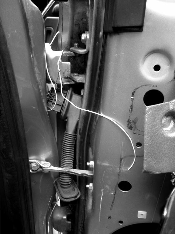 19. Push the end of the supply wire into the door cavity. Push the conduit grommet back into the door edge. Push the connector block and the conduit grommet back into the jamb. Replace the large footwell grommet. Bring the supply wire through the door membrane somewhere near the speaker pocket. Nick the membrane and feed it through. 20. Refit the membrane to the door frame using the mastic. Refit the speaker. You now have your supply wire inside the door as shown next. 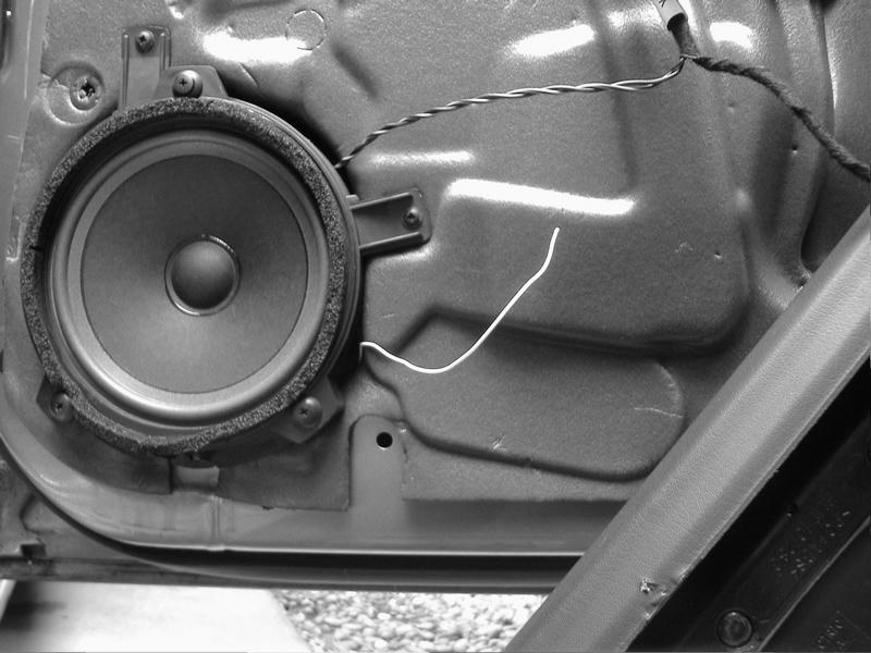 20. Repeat the above general procedure with each door that will have a puddle light. Fitting the Puddle Light Units a. The units are supplied with a 28mm hole saw to cut a mounting hole through the lower edge of the door card. I found the fit extremely tight. The 28mm hole requires some easing with a half-round file/rasp or you'll have difficulty fitting the lights. Be prepared for this. The hole saw would be better at 29mm. 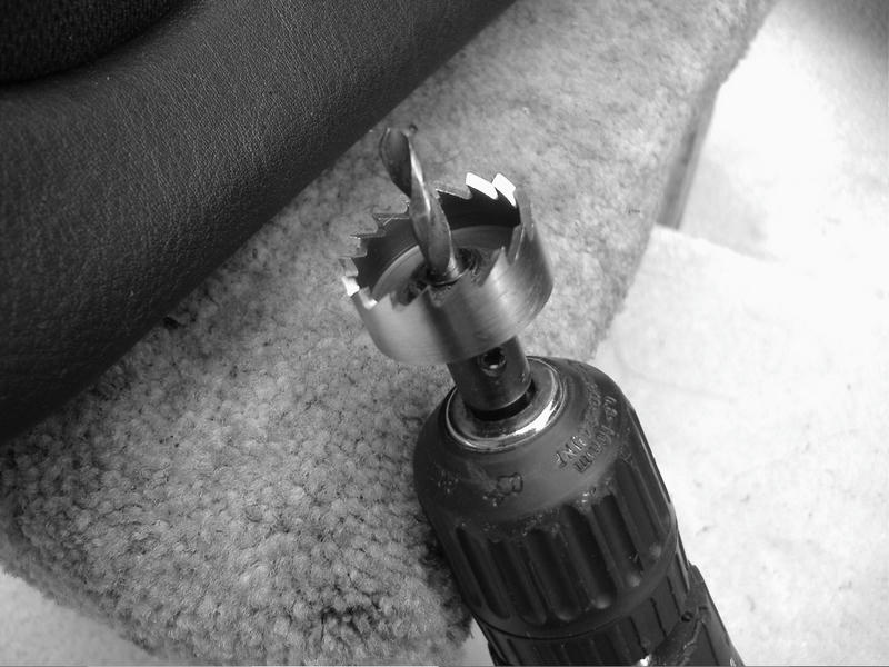 b. Carefully invert the door card so you can see the best place to locate the light unit. The base of the card is shaped/tapered, so you must place the centre for the drill on the wider horizontal part. If you try to mount it too close to the hinge end, the light won't fit. The exact place is your choice, but I think the best place is on the wider part nearest the centre. This puts the light beam as close to the door sill as possible. c. if necessary, use some masking tape on the outer face of the card to mark the drill centre point. It must be central on the width because there's precious little room for the light module inside. d. Using an electric drill, cut the hole through the card from outside inwards. A little ragging of the edge is unavoidable, but it will be covered by the lamp bezel. The hole saw is actually of good quality. 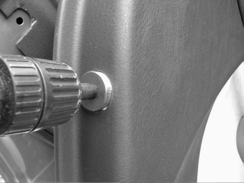 e. Test the fit of the lamp unit by removing its locking ring and pushing the wires/body into the card from the outside. If necessary, ease the fit by filing around the hole until the lamp moves easily. You need it to turn without the threads binding. This is so you can orientate the Rover/MG logo that's projected on the ground. 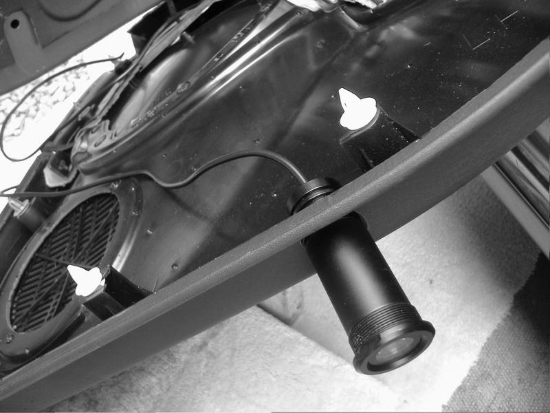 f. When you're happy with the fit, screw the internal holding ring onto the lamp unit but leave it finger tight. Don't lock it with the grub screw until you've set the logo beam orientation. g. The next step is connecting up the circuit. The lamps are supplied with a large amount of twin (red & black) flex, which you'll need to shorten to a suitable length. This is determined by the earth connection for the black wire from the puddle light. There's an earth lead in the door harness. The cable bunch from the lock, etc. has a single black earth wire which can be found by unwrapping the binding and separating the wires. With this done, cut a little of the plastic insulation so you can solder the black wire from the light to the earth. An alternative might be scotchlocks or similar, but the wires are quite fine. I recommend soldering the join if possible using heat shrink sleeving or insulating tape over it for support. h. The red wire from the puddle light is connected to your new supply wire, preferably by soldering them. Insulate the join. i. Temporarily refit the door card by hooking up the release cable and fitting the card onto the window ledge. You need the door to shut properly and open again with the handle. Shut the door. j. Reconnect the battery. k. Place a white sheet of some sort under the door so you can see the projected logo. l. Open the door and check that the puddle light comes on. The logo should be in focus, but may not be orientated as you'd like. The obvious orientation is so you can see/read the logo correctly as you prepare to exit the car. If it's not right, the light unit needs twisting round. m. With the door open, pull the card away at the bottom so you can grasp the light unit. Alternatively, the exterior bezel has flats to receive a spanner. Turn the unit so the logo is correctly displayed on the ground. n. Lock the light unit in position using the locking ring and then tighten the grub screw to stop it moving. o. Refit the door card using new card clips where necessary. p. Repeat all the above for each puddle light. q. Results are best seen in the dark! 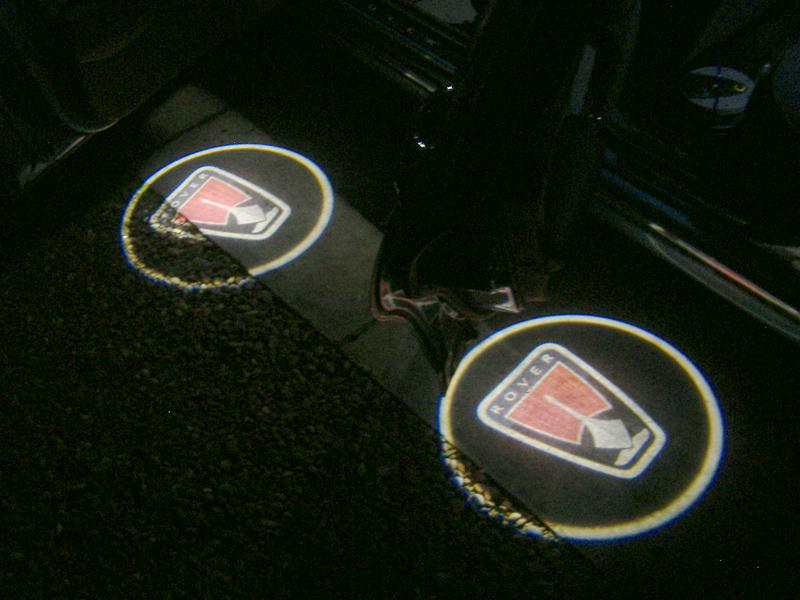 Note: The puddle light unit contains a tiny photographic transparency of your chosen logo. The LED beam is configured to produce an in-focus image over a wide range. There are five optical quality plastic lenses inside the unit which should be in the correct positions to focus the beam. One of mine was out of focus. Correcting this is difficult but it can be done with care. The unit can be opened up quite easily by unscrewing the LED carrier at the top end. Inside there's a split tube insert containing the optical system. If you don't take great care, the whole thing will disintegrate on removal and you'll never get things back without instructions. There are two large plano-convex lenses set up in a Plössl arrangement, followed by three unequal bi-convex lenses of smaller diameter. The clue to correct focus is in the orientation of thee small lenses. If anyone finds their logo to be blurred when projected onto a flat white surface, I will post the instructions for adjusting the focus. I really do hope nobody needs to do it! Disclaimer: You are responsible for any work or modifications carried out on your car and you undertake any such work at your own risk. Neither The 75 and ZT Owners Club nor the original author of these How-To's can be held liable for anything that may happen as a result of you following these How-To's. Any modifications should be reported to your insurance company. TC Last edited by T-Cut; 4th August 2017 at 18:44.. |

|

|
|
5th April 2013, 22:21
|
#2 |
|
This is my second home
None * DROWNED Join Date: Aug 2007
Location: Cardigan
Posts: 33,339
Thanks: 1,257
Thanked 1,664 Times in 1,081 Posts
|
Yet another prime bit of good work here TC
  Copied to here for posterity, with link back to this thread
__________________
Andrew Ich Dien Problem solving is... lateral thinking SEARCH FIRST ...ASK LATER...  |
|
|
|
|
5th April 2013, 22:31
|
#3 |
|
Regular poster
mgzt Join Date: Mar 2013
Location: st ives
Posts: 85
Thanks: 0
Thanked 0 Times in 0 Posts
|
Very very smart !
|
|
|
|
|
5th April 2013, 22:45
|
#4 |
|
This is my second home
Rover 75 2.5 V6 Connoisseur SE 4dr manual Wedgewood Blue 2 04-05/06/2001 Join Date: Nov 2006
Location: N.E. Hampshire
Posts: 4,617
Thanks: 289
Thanked 308 Times in 243 Posts
|
Very nice work there.
Just one question - would it not be possible to use the wiring already in the door that produces the 'door open' signal? Wouldn't this carry the neccessary 12v, if it could be identified? I'm hoping this is the case to try to save a lot of work that I want to avoid if possible. |
|
|
|
|
5th April 2013, 23:12
|
#5 | |
|
This is my second home
Rover75 and Mreg Corsa. Join Date: Nov 2006
Location: Sumweer onat mote o'dust (Sagin)
Posts: 21,752
Thanks: 341
Thanked 3,660 Times in 2,924 Posts
|
Quote:
Reading the advertising blurb for these indicates it's done by connecting the lamp wires to the door light/courtesy switch. Maybe it is on a twentyfive year old banger, but on ours cars (and most others too) it isn't that simple. It would be nice to get individual supplies rather than having all four light up when only one door is opened. The LEDs use very little juice though. TC Last edited by T-Cut; 6th April 2013 at 12:48.. |
|
|
|
|
|
6th April 2013, 09:29
|
#6 |
|
This is my second home
Rover 75 Saloon & Tourer Join Date: Sep 2012
Location: Lincoln
Posts: 14,912
Thanks: 1,630
Thanked 3,032 Times in 2,181 Posts
|
T-Cut, thank you for taking the time to make the post. I think my wife wants me to fit puddle lights
macafee2 |
|
|
|
|
25th April 2013, 21:56
|
#7 |
|
Loves to post
Rover 75 2.0 CDT Connoisseur Join Date: Dec 2012
Location: Hindhead
Posts: 263
Thanks: 17
Thanked 0 Times in 0 Posts
|
Where did u buy the lights?
I like the ideea, would be nice if i can put it into my sunroof saloon. |
|
|
|
|
26th April 2013, 11:31
|
#8 |
|
This is my second home
Rover75 and Mreg Corsa. Join Date: Nov 2006
Location: Sumweer onat mote o'dust (Sagin)
Posts: 21,752
Thanks: 341
Thanked 3,660 Times in 2,924 Posts
|
I bought them from Radioguy's shop. http://autogpsdvds.com/index.php?rou...product_id=150
I think it's the only place you'll get them with the Rover logo, certainly the Mk2 version. There's no reason why you can't run the power wires under the carpets and up to the door jambs. You can take the supply from an alternative place. There's a suitable connector in the passenger foot well. I forget the details, but it's well known. TC |
|
|
|
|
30th June 2013, 21:46
|
#9 |
|
Loves to post
MG ZT 1.8T 160 Xpower Grey Join Date: Jul 2010
Location: Aldridge
Posts: 355
Thanks: 8
Thanked 15 Times in 15 Posts
|
Finally had time to get these gen 4 ones with MG logo in with a temp setup
These ones only need an 18mm hole & were quite short so easy to mount on the door panel. Wrapped some foam around resisitor block and held it in place with a small o ring to remove any chance of cable knocking but that is probably OCD on my part  As I did not have time to route the wire to the roof unit, i tried them on the door window switch loom. Put a bit of solder on the wires as they are supermodel thin and cheap. Connected them to the red/white wire for + and the black for - turned the lights to get the logo facing where I wanted. Far too sunny to test so left it til tonight and Although its on gravel they seem fine. Will get some pics when I get it on solid floor or get some white paper to project on to. Checked there was no light bleed in or out of the car being as they will be on when the the lights are on and it was fine. So until I can get few more hours to tinker and get them routed up to the roof courtesy light & soldered in place it will do and looks good.
__________________
You don't need to own a sheep to know what not to put in it ! |
|
|
|
|
1st July 2013, 08:13
|
#10 | |
|
Gets stuck in
MG ZT CDTI +135 Join Date: Feb 2010
Location: Wilmslow
Posts: 566
Thanks: 36
Thanked 57 Times in 51 Posts
|
Quote:
|
|
|
|
|
 |
|
|


 Linear Mode

