
|
|
|
|
|
|
||
|
|
||
 9th June 2011, 08:44
|
#11 |
|
This is my second home
MGF Join Date: Mar 2010
Location: Boston
Posts: 4,865
Thanks: 123
Thanked 281 Times in 178 Posts
|
When Harry & Son did mine, I bought this
http://www.towsure.com/product/Smart_7_Way_CanBus_Relay Used this Image 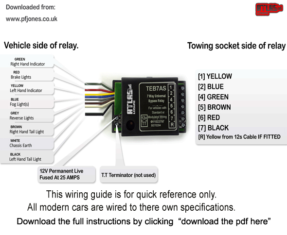 And then used this info that is specific to the car Left indicator = Green + PinkWorked a dream ever since  The above will give you Single Electrics, and its not plug and play. Simon
__________________
Si Kelsh |

|

|
|
9th June 2011, 16:50
|
#12 |
|
Loves to post
MG ZT-T CDTI Join Date: May 2010
Location: Newport
Posts: 384
Thanks: 7
Thanked 25 Times in 23 Posts
|
Thanks that's very helpful.
__________________
This vehicle was the 5,602nd ZT-T to run off the production line, out of 8,249 This vehicle was the 383rd ZT-T CDTi + (115) to be made out of 522 This vehicle was the 995th ZT-T in XPower Grey (code: LEF) to be made out of 1,673 XPower Grey ZT-Ts |
|
|
|
|
10th June 2011, 23:07
|
#13 | |
|
This is my second home
75 Contemporary SE Mk II 2004 Man. Sal. CDTi 135ps, FBH on red diesel, WinCE6 DD Join Date: May 2010
Location: Leeds
Posts: 17,273
Thanks: 2,160
Thanked 2,061 Times in 1,586 Posts
|
Quote:
If you want to actually wire up the supplementary socket, you will also need the voltage sensing relay. That simply switches the power on to the fridge and battery charge, as the voltage across the main battery rises, as the engine is started and turns it off when you stop the engine. Either fog lights or reversing lights (not sure which) also work via the supplementary socket. He also recommends that all connections and joint are properly spliced with solder plus heatshrink for reliability, rather than using those quick blue cable splicers.
__________________
Harry How To's and items I offer for free, or just to cover the cost of my expenses... http://www.the75andztclub.co.uk/foru...40#post1764540 Fix a poor handbrake; DIY ABS diagnostic unit; Loan of the spanner needed to change the CDT belts; free OBD diagnostics +MAF; Correct Bosch MAF cheap; DVB-T install in an ex-hi-line system; DD install with a HK amp; FBH servicing. I've taken a vow of poverty. To annoy me, send money. Last edited by HarryM1BYT; 10th June 2011 at 23:12.. |
|
|
|
|
|
11th June 2011, 08:52
|
#14 |
|
Loves to post
MG ZT-T CDTI Join Date: May 2010
Location: Newport
Posts: 384
Thanks: 7
Thanked 25 Times in 23 Posts
|
Thanks.
I don't need to really wire the S socket in as I am only towing a trailer but as all the insides of the boot need to come out I may as well wire it all in so if I ever do need it thene it's there. Thanks guys
__________________
This vehicle was the 5,602nd ZT-T to run off the production line, out of 8,249 This vehicle was the 383rd ZT-T CDTi + (115) to be made out of 522 This vehicle was the 995th ZT-T in XPower Grey (code: LEF) to be made out of 1,673 XPower Grey ZT-Ts |
|
|
|
|
11th June 2011, 09:15
|
#15 | ||
|
This is my second home
N/A Join Date: Feb 2010
Location: Suffolk
Posts: 6,867
Thanks: 0
Thanked 397 Times in 302 Posts
|
Quote:
Replaced with a decent crimp connection and all is good... solder is better but a crimp is just as good and a lot easier. WRT to power cables - you'll need about 6m of power cable to go from the battery to the boot (or at least 5m gets you to the rear seats). You could probably use 5m if you started at the passenger-side fusebox, though. I would use some larger wire (like this) just so if you ever need a little more power it's already there - my towbar is wired up with really really small cables and while thats fine for lights, it's not up to any sort of real load. Quote:
|
||
|
|
|
|
11th June 2011, 09:24
|
#16 |
|
Loves to post
MG ZT-T CDTI Join Date: May 2010
Location: Newport
Posts: 384
Thanks: 7
Thanked 25 Times in 23 Posts
|
So what is best....?
Take power straight from battery or from the fuse box? If from the battery how hard is it to feed the wires through the bulkhead? If the fuse box, what fuse do I use? Would 30amp cable be good enough?
__________________
This vehicle was the 5,602nd ZT-T to run off the production line, out of 8,249 This vehicle was the 383rd ZT-T CDTi + (115) to be made out of 522 This vehicle was the 995th ZT-T in XPower Grey (code: LEF) to be made out of 1,673 XPower Grey ZT-Ts Last edited by Graham E; 11th June 2011 at 09:29.. |
|
|
|
|
11th June 2011, 11:01
|
#17 |
|
This is my second home
75 Contemporary SE Mk II 2004 Man. Sal. CDTi 135ps, FBH on red diesel, WinCE6 DD Join Date: May 2010
Location: Leeds
Posts: 17,273
Thanks: 2,160
Thanked 2,061 Times in 1,586 Posts
|
You can take it from the battery, the main fuse box, or there is a feed already behind the glove box for the purpose - yellow/red (I think). Where ever you take it from, fit a 25 or 30amp for the supplementary supply and a 10amp for the road lights and as close to where ever you source the supply from as possible. Some suggest a 20amp fuse is adequate for the supplementary supply - with a thin cable and volts drop it might be, but a thicker cable with a fridge and a low battery at the end of it, it would likely blow in time. The 25amp will cope.
The problem isn't so much current capacity as voltage loss or drop along the cables. At 12v you cannot afford to drop much voltage.
__________________
Harry How To's and items I offer for free, or just to cover the cost of my expenses... http://www.the75andztclub.co.uk/foru...40#post1764540 Fix a poor handbrake; DIY ABS diagnostic unit; Loan of the spanner needed to change the CDT belts; free OBD diagnostics +MAF; Correct Bosch MAF cheap; DVB-T install in an ex-hi-line system; DD install with a HK amp; FBH servicing. I've taken a vow of poverty. To annoy me, send money. |
|
|
|
|
11th June 2011, 11:11
|
#18 |
|
Loves to post
MG ZT-T CDTI Join Date: May 2010
Location: Newport
Posts: 384
Thanks: 7
Thanked 25 Times in 23 Posts
|
If there is a wire already in place is this connected to the fuse box? If so which fuse?
Is it good enough to take the feed to the lights via one wire and the charging via another?
__________________
This vehicle was the 5,602nd ZT-T to run off the production line, out of 8,249 This vehicle was the 383rd ZT-T CDTi + (115) to be made out of 522 This vehicle was the 995th ZT-T in XPower Grey (code: LEF) to be made out of 1,673 XPower Grey ZT-Ts |
|
|
|
|
11th June 2011, 12:35
|
#19 | ||
|
This is my second home
N/A Join Date: Feb 2010
Location: Suffolk
Posts: 6,867
Thanks: 0
Thanked 397 Times in 302 Posts
|
Quote:
Theres a grommet next to the bonnet release you can use if you decide to go through the bulkhead. Quote:
|
||
|
|
|
|
23rd June 2011, 22:25
|
#20 |
|
This is my second home

75 model car Join Date: Apr 2011
Location: Newcastle upon Tyne
Posts: 20,177
Thanks: 4,008
Thanked 5,083 Times in 3,114 Posts
|
I wired my towing sockets direct to the harness in the boot,ie scotchlocked onto the corresponding wire for the lights ,and the auxiliary socket the same way live to live earth to the body etc including the s/c relay,been like that for two years ,no probs
__________________
Cheers. Rich |
|
|
|
 |
|
|


 Linear Mode

