
|
|
|
|
|
|
||
|
|
||
 20th March 2012, 12:11
|
#1 |
|
This is my second home
Rover75 and Mreg Corsa. Join Date: Nov 2006
Location: Sumweer onat mote o'dust (Sagin)
Posts: 21,753
Thanks: 341
Thanked 3,660 Times in 2,924 Posts
|
How To - Understand Fuel Tanks (Last edited 21 August 2014)
This is another bit of work in progress and there are probably things I've got wrong. Hopefully these will be corrected through informed comment. I'll edit it as additional info is gathered and mistakes are corrected. Over the years, I’ve read loads about what happens in the fuel tank if for example, a diesel pump fails, or Fuel Filter Syndrome (FFS) develops in a petrol system. Thankfully there are only a few different problems, but they do happen frequently and they get discussed a lot. However, I’ve often felt the explanation of cause and effect is little more than guesswork or misinterpretation. So, I decided to learn what I could about the way tanks work and did some research. I admit I was surprised. Boiling it down, I thought a simple fluid flow diagram for the fuel tanks would be useful. Basically, if you understand the flow paths you can explain the things that happen. What surprised me is the fact that all fuel tanks contain not one, but three pumps. In addition to the electric pump located in the RHS of the tank, there are two static pumps located deep inside the plumbing system. These transfer fuel within the tank and ensure the electric pump inlet is always submerged, no matter what the fuel inventory or the driving conditions. Now this seems contrary to many things I’ve read on the forums, especially regarding diesels. The ‘quarter tank’ rule for diesels has always intrigued me and I now see the explanation of it. Similarly, the idea that under certain circumstances the RHS of the tank will have all its contents transferred into the LHS seems an illogical design feature. So I made some drawings of the petrol and diesel tanks to simplify the workings. 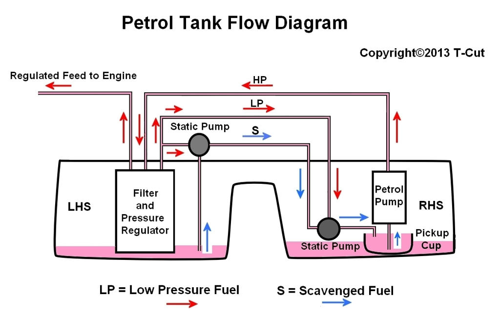 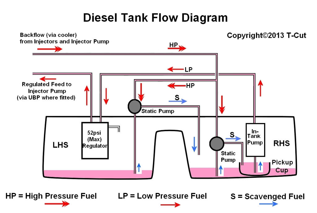 These show only the liquid flows. Vapour and pressure handling are omitted. The saddle tank and interior pipework are shown diagrammatically, so all this stuff is a bit different in reality. The idea behind the internal plumbing becomes apparent when the fuel level is below the central dividing hump. It makes most sense when the fuel inventory is very low, so the drawings show that situation. Diesel or petrol, the system is identical in principle, but the way it’s done is slightly different. The primary electric pump, whether diesel or petrol, is a centrifugal (impellor)type. The diesel one generates around 30psi at the outlet when in top condition. The single petrol pump generates around 50psi. The UBP in the diesel is a positive displacement type with a 'pigtail' gear design. A centrifugal pump can run against a closed outlet while maintaining its delivery pressure, but it must be adequately primed. To ensure this, the pump is fed from a permanently flooded pickup or swirl cup. It’s the job of those other two pumps to keep the swirl cup full. When there's plenty of fuel in the tank, the electric pump and its swirl cup are completely submerged, so while there are transfers happening within the tank, they only become important when the inventory falls. At very low inventory, any air getting into the pump inlet is vented off at the upper end of the pump through a scavenger/priming valve which closes when the pump is hydraulically locked. Make note of this valve. The two secondary in-tank pumps are static inductors based on the Venturi principle. These get their motive power from pressurised fuel generated by the electric pump (petrol) or the diesel’s HP injector pump back-flow from the engine. Their sole purpose is to ensure the swirl cup remains full under all conditions. Since they will only work when pressurised fuel is fed into them, any circumstance which reduces this pressure will cause a tank malfunction. For example, the diesel HP backflow passes through the cooler mounted externally near the tank. A fuel leak from the cooler may inhibit delivery from the inductors. Similarly, FFS in the petrol tank may inhibit feed to the inductors. This will also cause tank malfunction and explains why FFS is sometimes accompanied by an absence of fuel in the RHS. Diesels with two electric pumps (ITP and UBP) may under certain conditions fail to get sufficient fuel if one fails. The ITP has adequate delivery capacity when assisted by the UBP. So, when it has to work alone, it needs to do the work of the UBP as well. Whether it copes with the load depends very much on the lift it has to cope with. The lift of a pump is determined by the outlet pressure. The required lift is the vertical height between the fuel surface in the tank and the HP pump inlet on the engine. While the height remains below some critical point, fuel will get to the engine. The only variable in this equation is the fuel level. As the level drops, the required lift increases, until a point is reached where delivery fails. I assume this is at the nominal quarter tank level. As fuel delivery reduces, the volume of HP backflow from the engine will fall. This backflow is vital for the correct handling of fuel by the Venturi pumps. As noted, these scavenge fuel from the left side of the tank into the right and from there into the ITP swirl cup. Clearly, if the scavenger pumps are inoperable due to lack of HP backflow, the RH side of the tank will run dry. If the ITP fails before the UBP, this has to lift fuel from the tank and deliver it to the HP pump on the engine. I would guess then, that the UBP is a different type from the ITP and is logically positive displacement. (This has subsequently been confirmed and there are some nice photos (somewhere) of the interlocking spiral worm gears). It must have sufficient 'suction' to raise fuel from the tank (via the dead ITP) on startup. It would be interesting therefore to compare the innards of each. Again, the quarter tank rule seems to apply, so that the UBP can cope with the lift and engine requirements. As the UBP eventually fails, the scavenger pumps fail and fuel seemingly becomes transferred the LHS of the tank. Later diesels only have a single primary pump (ITP). I believe this is a higher spec'd type and presumably has the lift and capacity to cope with the demands of the engine and the tank scavenging system. When this pump starts to fail, you'd expect the outcome in terms of fuel distribution to follow a similar pattern. It would seem logical in cases of double pump failure to replace the ITP with the later type and simply bypass the UBP. Apparently this isn't possible, I assume because of design differences between the two. (??) The following discussion raises the question of the fuel cooler fitted in the diesel system. This isn't shown in the above drawing to keep it simple, but there are some implications if it goes wrong. An example of this can be found here: https://www.the75andztclub.co.uk/for...d.php?t=193016 TC Last edited by T-Cut; 16th July 2017 at 13:48.. Reason: Images released from the Photobucket ransom plot. |

|

|
|
20th March 2012, 15:06
|
#2 |
|
Owners Club Director

Rover 75 Conn SE V6 / MG ZT 260 SE V8 / MG ZT 180 SE V6 Join Date: Feb 2007
Location: Southampton
Posts: 20,948
Thanks: 645
Thanked 6,851 Times in 2,537 Posts
|
Excellent post T-C, you say it's a work in progress and subject to revision. The How To section is deliberately locked to keep all the threads uncluttered and clear for reference purposes.
When you are happy for it to be placed in there, let a mod know, and we will make a copy of it to be kept there for future reference. Your live thread will of course remain here for comments and amendments. |
|
|
|
|
20th March 2012, 19:37
|
#3 |
|
This is my second home
Rover 75 CDT Manual Connoisseur SE, Rover 75 CDT Automatic Connoisseur SE & a Freelander Td4. Join Date: Jul 2009
Location: Hampshire
Posts: 11,560
Thanks: 3,470
Thanked 3,119 Times in 2,247 Posts
|
Good start TC but I think you need to add the fuel cooler, thermostatic valve and the associated pipework to the diesel circuit, because when the fuel is cold I don't think it returns to the tank but stays in a closed loop circuit, with the ITP topping up what is taken by the HP pump to fuel the engine. Overspill from the ITP returns to the tank during this time.
If you look closely at the circuit there isn't a simple bypass of the fuel cooler to the tank, and the way it is piped, taking into account the different pressures from the returning fuel and the ITP, it diverts fuel straight back to the UBP which gets it up to temperature in cold climates alot faster, then as everything warms up the thermostatic valve starts to open to regulate fuel through the fuel cooler and back to the tank. One other point is that with a failed UBP the engine stops. The ITP can't supply fuel past the UBP. A good UBP will run fine with a failed ITP with enough fuel in the tank, although it has more work to do. The system is a bit more clever than it looks! Mike Last edited by Mike Noc; 17th August 2014 at 22:10.. |
|
|
|
|
20th March 2012, 21:03
|
#4 | |
|
This is my second home
Rover75 and Mreg Corsa. Join Date: Nov 2006
Location: Sumweer onat mote o'dust (Sagin)
Posts: 21,753
Thanks: 341
Thanked 3,660 Times in 2,924 Posts
|
Quote:
EDIT: I did think twice about the results of ITP and UBP failure on fuel delivery, but I feel certain I've read of engines running on the UBP alone. I'll have to go back to that for sure. TC Last edited by T-Cut; 20th March 2012 at 21:15.. |
|
|
|
|
|
20th March 2012, 21:22
|
#5 | |
|
This is my second home
Rover 75 CDT Manual Connoisseur SE, Rover 75 CDT Automatic Connoisseur SE & a Freelander Td4. Join Date: Jul 2009
Location: Hampshire
Posts: 11,560
Thanks: 3,470
Thanked 3,119 Times in 2,247 Posts
|
Quote:
It was your quote here that maybe I misunderstood: [Quote] Diesels with two electric pumps (ITP and UBP) may under certain conditions fail to get sufficient fuel if one fails. The ITP has adequate delivery capacity when assisted by the UBP. So, when it has to work alone, it needs to do the work of the UBP as well. Whether it copes with the load depends very much on the lift it has to cope with. [QUOTE] Mike |
|
|
|
|
|
21st March 2012, 00:08
|
#6 |
|
Posted a thing or two
Rover 75 Tourer Join Date: Nov 2006
Location: Malpas
Posts: 1,526
Thanks: 34
Thanked 118 Times in 89 Posts
|
Quote ' I would guess then, that the UBP is a different type from the ITP and is logically positive displacement. It must have sufficient 'suction' to raise fuel from the tank (via the dead ITP) .'
Open to correction here, but surely the UBP is the same as the ITP, Both look the same type, long cylindrical. The UBP is of the double interlocking helical type. That cant be positive displacement ? or can it ?. |
|
|
|
|
21st March 2012, 06:52
|
#7 |
|
This is my second home
Rover 75 CDT Manual Connoisseur SE, Rover 75 CDT Automatic Connoisseur SE & a Freelander Td4. Join Date: Jul 2009
Location: Hampshire
Posts: 11,560
Thanks: 3,470
Thanked 3,119 Times in 2,247 Posts
|
They are different designs - as you say the UBP is a type of screw pump but the ITP has a rotary impeller.
The ITP is self priming due to a normally open ball valve situated at the top of the pump, allowing diesel to flow in. This closes as the pump pressure builds up. This means that with a failed ITP the ball valve is open so the UBP doesn't actually have to suck fuel through the ITP itself. It also means that when the fuel level drops down below the top of the ITP the UBP will start sucking air. Another clue to why the car can stop with a quarter tank of fuel onboard after the ITP has packed up. Mike Last edited by Mike Noc; 21st March 2012 at 07:01.. |
|
|
|
|
21st March 2012, 08:10
|
#8 |
|
This is my second home
Rover75 and Mreg Corsa. Join Date: Nov 2006
Location: Sumweer onat mote o'dust (Sagin)
Posts: 21,753
Thanks: 341
Thanked 3,660 Times in 2,924 Posts
|
Thanks Mike and Derek for your input. As more insights are gathered, I'll amend the account to make it more accurate. However, I don't want to make it more complex. The important thing is that the basic mechanisms are explained without too much detail of how they're managed. I see that the IPT/UBP inter-relationship does need some work.
TC |
|
|
|
|
21st March 2012, 09:02
|
#9 |
|
This is my second home
75 Contemporary SE Mk II 2004 Man. Sal. CDTi 135ps, FBH on red diesel, WinCE6 DD Join Date: May 2010
Location: Leeds
Posts: 17,273
Thanks: 2,160
Thanked 2,061 Times in 1,586 Posts
|
Very well done T-cut, it is the first time the fule system mystery has made any real sense to me.
A couple of questions.... I don't think the ITP pump type would generate anything like 52PSI, so why a pressure regulator there and are you suggesting that the regulator is actually in the tank? If it is indeed there, between ITP and UBP - why there, surely it would have been more sensible to have a regulator after the UBP? The T, where the HP return flow goes back to the tank - I don't a simple T piece would work to share the flow between the two venturi pumps would it, without some extra help to force it to share the flow? When that ITP does fail, might a second UBP in the line from the tank, make up for the failed ITP? The UBP is perfectly capable of self priming I found, from bench testing one. OK four questions  Must admit I had not thought of venturi pumps to pump fuel from one side of the tank to the other. So I suppose due to the venturi pumps needing pressure to work, that the return system and cooler must be under some pressure?
__________________
Harry How To's and items I offer for free, or just to cover the cost of my expenses... http://www.the75andztclub.co.uk/foru...40#post1764540 Fix a poor handbrake; DIY ABS diagnostic unit; Loan of the spanner needed to change the CDT belts; free OBD diagnostics +MAF; Correct Bosch MAF cheap; DVB-T install in an ex-hi-line system; DD install with a HK amp; FBH servicing. I've taken a vow of poverty. To annoy me, send money. |
|
|
|
|
21st March 2012, 10:35
|
#10 | |||||
|
This is my second home
Rover75 and Mreg Corsa. Join Date: Nov 2006
Location: Sumweer onat mote o'dust (Sagin)
Posts: 21,753
Thanks: 341
Thanked 3,660 Times in 2,924 Posts
|
Quote:
 This is Item 5. The pressure regulator is calibrated to 52psi, but remains shut under normal operation. Exactly what abnormal event would open that I've not figured out. I think Mike will know. I've amended the text to reflect the correct spressure. Quote:
Quote:
Quote:
Quote:
TC |
|||||
|
|
|
 |
|
|


 Linear Mode

