
|
|
|
|
|
|
||
|
|
||
 29th July 2019, 19:07
|
#31 |
|
Doesn't do things by halves
Rover 75 2.5 Connoisseur Auto (1999) Dealer launch model. Join Date: Mar 2007
Location: Former Middlesex
Posts: 20,378
Thanks: 1,587
Thanked 3,749 Times in 3,181 Posts
|
Zickleer; thank you for the photos and description which are enormously helpful.
Steve; thank you for collating the pictures and information into post no. 28. This makes it a whole lot easier to follow. Dave; thanks for joining in the investigation! An extra good mind is very welcome. I have drawn out the modified circuit and here are my findings. 1. The MG Rover control box, relays and resistor are completely out of circuit.  2. The fan motor is controlled by the RL-150B 12v 75A unit which is a relay. 3. This relay's coil is powered by the red wire (via a black 'socket') getting its supply from one of the car's original fan connectors. I can't see the exact connection but it must be from the YU wire which is ignition controlled. 4. The relay coil is earthed by its white wire. 5. The relay contact is supplied with 12v from the car's original thick brown wire. 6. When the relay contacts close, 12v is applied to the red then slate wires to the white block 'connector'. From here it is applied simultaneously to the motor's red and green wires. 7. Dave's deduction that red and green represent two speeds is very likely. 8. The motor is earthed via its black wire. So this is why Zickleer's fan runs continuously. It's nothing to do with the coolant temperature sensor. The fan's been wired to run whenever the ignition is switched on. What do we do to undo this awful mess and restore the fan to be under the control of the car's ECM and control box? I think Dave's suggestion is a good one. If a loom can be sent out to Zickleer with detailed instructions of how to connect it to the control box and his existing fan, he should end up with a 2 speed system controlled by the car and not a single speed bodge fed from this aftermarket RL-150B relay. How does that sound to you Zickleer? Simon
__________________
"Whatever is rightly done, however humble, is noble." Sir Henry Royce. Last edited by SD1too; 29th July 2019 at 19:12.. |

|

|
|
29th July 2019, 23:21
|
#32 | ||
|
Give to Learn

Freelander 2 Join Date: Aug 2010
Location: West Midlands
Posts: 18,716
Thanks: 1,155
Thanked 6,407 Times in 3,874 Posts
|
Quote:
HI Simon/Dave After looking at the control box it is definitely a two wire 2 speed control box & wiring, so why they changed all the wiring about I don't know, unless the fam motor had burnt out, which could be the reason a different fan blade/motor as been fitted. It also looks to me that there is enough wiring counting the wiring used to connect the wrong gold resistor which we think could be 50w as opposed to 100w, to make up a loom once the fan is off the car and on a work table. As we know the brown thick wire would join into the red wire going into the fan motor on the original two wire 2 speed fan, so we need to know which wire the thick brown wire needs to join on this fans motor Red or green as I am presuming the black wire coming from the motor is earth. We know the grey wire coming from the control box goes to the Gold resistor. The red wire coming from the control box joins a black wire which then splits into two black wires, one going to the resistor, the other going into the fan motor of the original two wire 2 speed fan, so which wire would it join to on this fan black/green or red ? One other wire to look at is the thick red wire that seems to join a thin wiring coming from the cars loom that can be removed altogether do we agree? and maybe follow the thin wire to see which wire as been cut. But we really need this fan off the car and all conduit removed.
__________________
Arctic Givology Learn to Give Everything is Achievable  ad altiora tendo. Check out our Nano meet dates http://www.midlandsnanomeets.co.uk/ http://www.the75andztclub.co.uk/index.php?thepage=howto " You do the work , we supply the expertise " |
||
|
|
|
|
30th July 2019, 05:09
|
#33 |
|
Newbie
mg Join Date: May 2014
Location: kl
Posts: 13
Thanks: 10
Thanked 1 Time in 1 Post
|
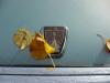
Thank you fellow Roverians once more the big help. Here are some additional photos. I am using the cheap ebay 100w 0.5ohm resistor. I tried to remove the fan itself but it seems the middle is held on by a brass clip/pin. Dare not remove it as I am afraid that the fan alignment would be off when refitting (a case of fear of making things turn from bad to worse).
I will gather all these gems of replies from Arctic, Simon and Dave to my mechanic and see what magic can he pull off 😊 Many thanks once more 👍👍👍 https://ibb.co/kXVdjxy https://ibb.co/fFNXtDm https://ibb.co/9WKyFM6 |
|
|
|
|
30th July 2019, 05:15
|
#34 |
|
Newbie
mg Join Date: May 2014
Location: kl
Posts: 13
Thanks: 10
Thanked 1 Time in 1 Post
|
Apologies, the black conduits are crimped using brass terminals from the feels of the connection. The heat shrink sleeves over it is quite thick, would need to slice it iopen with a pen knife. But can confirmed that in the conduit, brass crimp terminals are used to connect the wires.
Very optimistic that these replies from all Roverians will aid my mechanic a lot 😊👍 |
|
|
|
|
30th July 2019, 08:00
|
#35 |
|
Vis Whiz

Rover 75 2.5 auto Saloon Join Date: Jun 2007
Location: LEEDS
Posts: 20,590
Thanks: 2,057
Thanked 3,056 Times in 1,621 Posts
|
The blades do not need to come off the fan, undo the three bolts on the rear of the motor and it will all come out from the front along with the relay box etc..
It really depends on what you want to do now. Do you simply want a fan that runs or do you want to revert back to the original set up (using the fan you have). We can supply the information you require to return the wiring back to standard but in the end it is your decision 
__________________
Dave...  Lost a few stones and a Gall Bladder and part of a bile duct and all of my dignity in the suppository incident
|
|
|
|
|
30th July 2019, 08:02
|
#36 | |
|
Give to Learn
Freelander 2 Join Date: Aug 2010
Location: West Midlands
Posts: 18,716
Thanks: 1,155
Thanked 6,407 Times in 3,874 Posts
|
Quote:
Hi Jimmy. When I/we refer to black conduit it is these with yellow dots in the photo below, you may have to snip/cut the cable ties with little blue dots.  1 1 2 2Your fan is definitely not an original Rover 75 fan motor  3 3 4 4The gold resistor is also wrong  5 5It should be one of these  6 6 7 7
__________________
Arctic Givology Learn to Give Everything is Achievable ad altiora tendo. Check out our Nano meet dates http://www.midlandsnanomeets.co.uk/ http://www.the75andztclub.co.uk/index.php?thepage=howto " You do the work , we supply the expertise " Last edited by Arctic; 30th July 2019 at 08:21.. Reason: Photo Editing |
|
|
|
|
|
30th July 2019, 08:28
|
#37 | |
|
Doesn't do things by halves
Rover 75 2.5 Connoisseur Auto (1999) Dealer launch model. Join Date: Mar 2007
Location: Former Middlesex
Posts: 20,378
Thanks: 1,587
Thanked 3,749 Times in 3,181 Posts
|
Hi Steve,
Thanks for your very clear summary. I agree that the control box is the later 2 speed type. I noticed that the lid is marked PWM2 confirming this. Thanks to Zickleer's latest photos, the fan is definitely not a 75/ZT type. Whether it will move the required volume of air remains to be seen. Regarding using the existing motor connections with the MGR control box, they would remain exactly as they are. The thick brown high current supply wire (currently going to the RL-150B) would feed both motor red and motor green wires. The speed is controlled by the resistor, just as an MG Rover Siemens motor is.  Alternatively, the resistor could be dispensed with and the two control box relays used to trigger what we believe to be two windings on the existing fan. This would involve some rewiring and deviation from the MGR circuit so is probably best avoided for simplicity. However, if Zickleer's mechanic would like me to list the modifications to achieve this, I'd be happy to do so. Quote:
So to summarise; the motor supply is to red and green simultaneously and the motor earth (black) goes to the control box relay red wire and the resistor. I'd like to identify the thick red wire that seems to join a thin wire coming from the cars loom before removing it. Can Zickleer tell us the colour of the thin wire and where the two connections are? I believe that the rectification work you suggest can be done Steve without removing the fan from the car. As it's an aftermarket bodge, removing it might cause additional problems. Any comments? Simon
__________________
"Whatever is rightly done, however humble, is noble." Sir Henry Royce. Last edited by SD1too; 30th July 2019 at 08:43.. |
|
|
|
|
|
30th July 2019, 10:05
|
#38 |
|
Vis Whiz
Rover 75 2.5 auto Saloon Join Date: Jun 2007
Location: LEEDS
Posts: 20,590
Thanks: 2,057
Thanked 3,056 Times in 1,621 Posts
|
OK, Happy to take on board any comments but this is how I see it.
You need to go back to the main plugs for the wiring, there are two of them. Each plug will have one heavy duty wire, one black and one brown. These are the two main wires shown below. Strip out the RL 150 and remove. Hoping/assuming that all the light duty wires in the plugs are still connected at the main plugs and control box ( There are three of them) then this is the wiring for the fan and resistor I have put together for the fan you have. [IMG]  [/IMG] [/IMG]So, in summary
NB disconnect the plugs from the car harness before working in the wiring.
__________________
Dave... Lost a few stones and a Gall Bladder and part of a bile duct and all of my dignity in the suppository incident
Last edited by stocktake; 30th July 2019 at 10:08.. |
|
|
|
|
30th July 2019, 18:40
|
#39 |
|
Give to Learn
Freelander 2 Join Date: Aug 2010
Location: West Midlands
Posts: 18,716
Thanks: 1,155
Thanked 6,407 Times in 3,874 Posts
|
cartoon picture of the wiring layout Dave posted above, I am sure Jimmy's mechanic should be able to follow one or both of them
 it still need the large red wire connected to the thin wiring of the cars loom to be investigated/ removed before any work is carried out. it still need the large red wire connected to the thin wiring of the cars loom to be investigated/ removed before any work is carried out.  1 1
__________________
Arctic Givology Learn to Give Everything is Achievable ad altiora tendo. Check out our Nano meet dates http://www.midlandsnanomeets.co.uk/ http://www.the75andztclub.co.uk/index.php?thepage=howto " You do the work , we supply the expertise " |
|
|
|
|
2nd August 2019, 10:01
|
#40 |
|
Newbie
mg Join Date: May 2014
Location: kl
Posts: 13
Thanks: 10
Thanked 1 Time in 1 Post
|
Wow systems all good to go 👍 followed your advice Arctic on routing the grounded cable to the resistor and now the fan is off when on ignition and only starts when demist test is done 👍
Apologies once more for being MIA and many thanks to all that helped out. 🙏🙏 |
|
|
|
 |
|
|


 Linear Mode

