
|
|
|
|
|
|
||
|
|
||
 12th February 2010, 19:15
|
#1 |
|
This is my second home
Rover 75 Saloon Join Date: Aug 2007
Location: Avignon
Posts: 4,466
Thanks: 94
Thanked 661 Times in 554 Posts
|
MY STORY:
I came upon this Forum 3 years ago after my in tank fuel pump broke. I found advice here to have my pump quickly and cheaply repaired. I too also had the strange Fuel Burning Heater (FBH) behaviour caused by the K bus. (Which I have since disconnected.) As a regular reader, I have noted lots of threads about FBH issues and in particular that the PCB was reported as being non repairable. The cold days made me inclined to study the question. I began by trying to collect information about the circuit diagram etc, (not very easy) At first I thought the Interface IC bus was the culprit. I ordered the genuine interface IC bus (ELMOS 10026B) from Hong-Kong, but one month later, nothing ;they forgot to ship Meantime, I bought the Riesler interface Bus describe by Keith Alexander . I discovered than his Interface Bus IC was a (Melexis TH3122) similar and more easy to get. Next, I built up a test bench and established communication between my laptop and the Webasto PCB. However, there was a combustion air fan error. (running at max speed). Tracing the PCB ‘tracks’, I discovered than the power Mosfet’driver was always ON although the Micro bus line concerned was live .The link is in fact a SMD (surface mounted) resistor well hidden under a kind of sticky sealant (looks like meringue.) The resistor was marked 4.75 kOhms but my multimeter showed infinite ! Strange ,I had rarely seen that before in my professional live. Anyway, I quickly replaced it and …..everything worked ….. I opened a new thread on the forums to tell the news. So, the only possible cause, was that the resistors were being attacked by a chemical agent from that paste (meringue). (can you imagine how many Webastos this may have affected all over the world !!) I would like to freely publicise this valuable information, in the true spirit of the ‘Forum’ and it’s ethos of sharing information. Most members will be able to do the work for themselves ( or know a man that can!). However, I can do the repair for others who don’t feel like tackling the job themselves TOOLS NEEDED: Low power soldering iron with thin tip correctly earthed. Table magnifier, Solder SM (surface mounted) resistors 4.7 Kohm ; 47Kohm PROCEDURE Extract the PCB from the FBH (5 screws) Pic 1  Remove that sticky white paste and clean the area to show the resistors. Take a measurement of them: two 4.75 Kohm and one 47 Kohm. Pic2  If possible, built a test bench for checking out all the parameters before fitting on car. Pic3 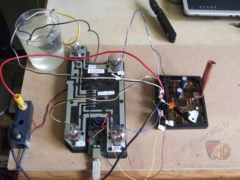 Results Pic4  Enjoy your warmer car  :lol: :lol:Mike Last edited by Dragrad; 22nd January 2016 at 00:31.. |

|

|
|
|


 Threaded Mode