How to Remove and Dismantle the Numberplate Lamp Unit
These notes/photos are based on the facelift/Mk2 model Rover 75. Other models may vary slightly.
I'd fitted a pair of 8xSMD LED festoons to illuminate the numberplate and was generally pleased with them.
They were reasonably cheap and didn't affect the blown bulb display at all. They weren't sold as CANbus friendly, which usually inflates the price. Anyway
after a few weeks one went out, which I thought was odd and a few weeks after that, the other also went out. Knowing that LEDs don't blow like bulbs, I decided that the wintry weather had got into the works and anticipated having tofix the printed circuit board I'd read about. This is the usual cause of numberplate lamp problems. So, here's myphoto record of the job.
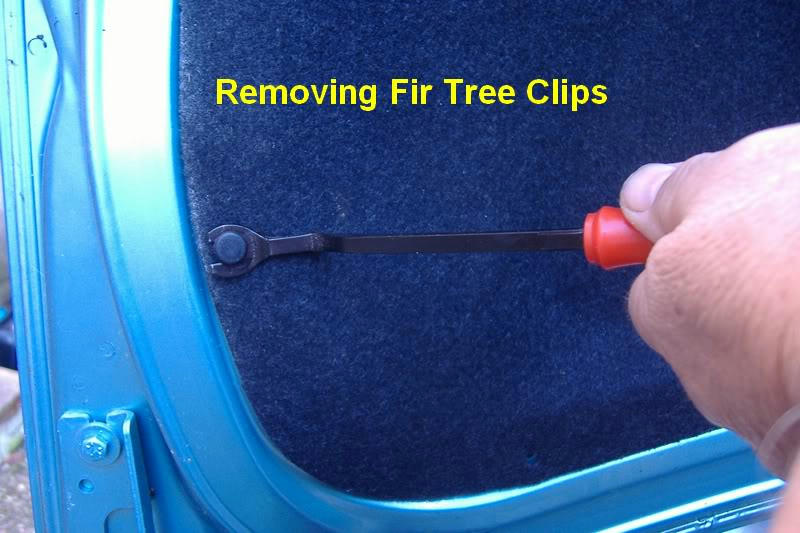
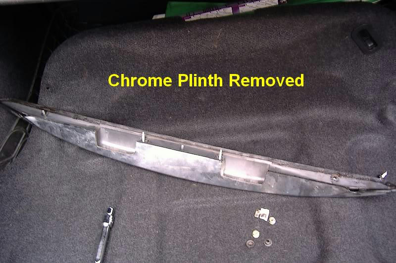
The numberplate lamp unit is housed within the boot lid lift handle or plinth as I call it. The plinth has to be removedfirst. To access the attachments, you have to remove the lid liner.
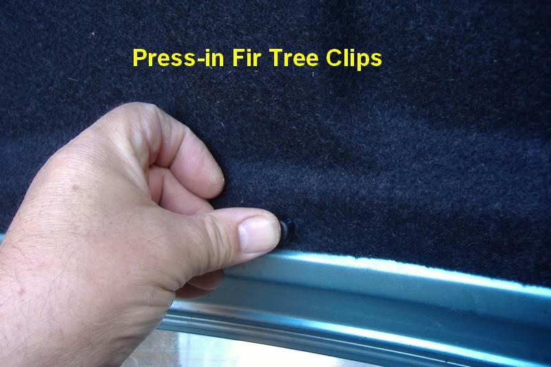
The liner is held in position by nineteen push fit (fir tree) clips around its edge. You can lever under the head of these with a thin blade. I happened to have a fir tree clip lifting tool as shown in the photo.
Image 1
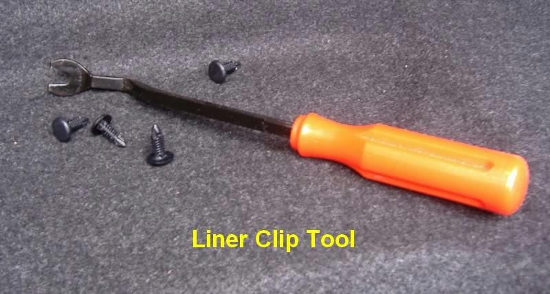
Here's another look at it. I bought this on eBay for a couple of pounds. It's ideal for removing door liner clips, which can be difficult.
Image 2
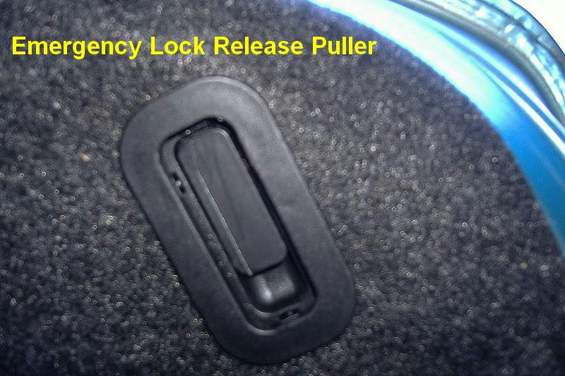
While removing the liner, you'll notice a plastic insert in the upper right corner. This is the emergency boot lockrelease. Yep, you can release a locked boot from inside by dropping down the rear seat squab. Remember that next timeyou lock the keys in the boot. Of course the doors must be unlocked so you can get inside, but it happens. Here's the release puller tab. It slides out of the holder and is attached to the lock with a tough plastic pull-string.
Image 3
Here it is after removing the liner.
Image 4
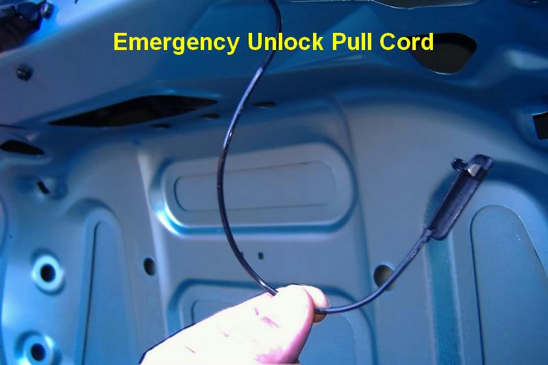
With the liner out of the way, you'll find a large opening through which you can pull away the two spade connectors forming the circuit. One is feed,
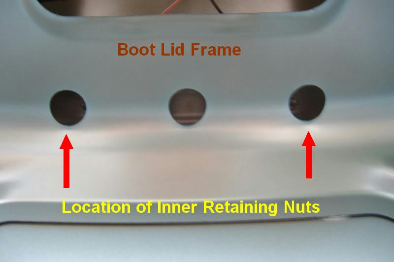
the other earth. They'll fit either way, but naturally stay in position. Next, remove the plinth retaining nuts.
There are two conventional flanged nuts either side of centre and two unconventional 'screwits' (my name) at each end. They each require a 10mm socket. The inner nuts are accessed
through holes in the boot lid framework as shown below.
Image 5
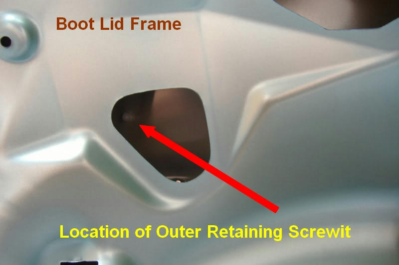
The outer fasteners are accessed through these orifices.
Image 6
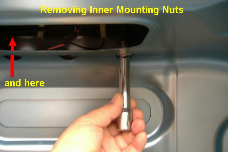
You may need a small torch to see into the cavity of the lid. Also, before applying the socket, put some sticky stuff into the socket to hold the nuts when they come away. If you drop one into the cavity of the lid, you'll never see it again. For this, I used some very sticky mastic strip designed for fixing double-glazing panels. Again, I happened to have a roll in the garage and decided it was also ideal for refitting the lamp. More on this later.
The nuts aren't tight, just slacken them by hand as shown below.
Image 7
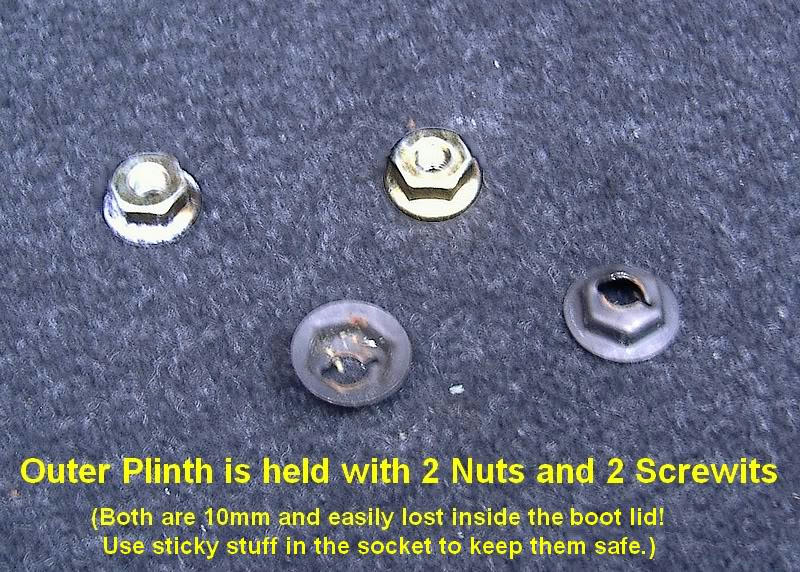
The inner nuts will come nicely off the captive bolts in the plinth. The two outer screwits need more care because they cut their own thread into the plastic pins at each end of the plinth. Here's the four nuts after careful removal.
Image 8
Here's a closeup of a screwit so you can get the gist of it.
Image 9

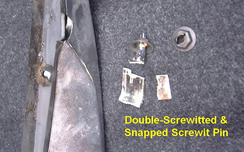
These screwits are basically designed for single use only so a little damage may be caused to the pin when you unscrew them. You have to use some judgement on how much stress to apply, particularly when refitting them.
With all four nuts removed, the plinth will simply lift away from the lid. Or at least it shoul. In my case the left end seemed stuck. I assumed the plastic pin was somehow fouling the lid and no amount of gentle pulling would free it. When I looked againusing the torch, there was another screwit still holding onto the pin! They'd screwed two on instead of one! I guess they were nested together when they guy fitted it all. Anyway, that possiblity is worth knowing about and will prevent you damaging thepin as I did. It snapped off during the struggle. Here's the bits.
Image 10
and close up:
Image 11
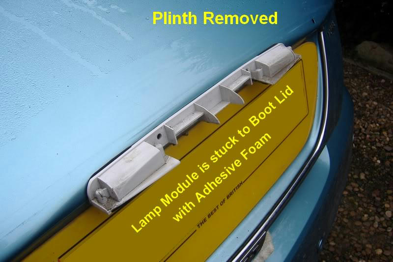
With the plinth removed, you'll find the innerlamp unit attached to the lid. It's suck in place with double-sided sticky foam - and it's very well stuck!
Image 12
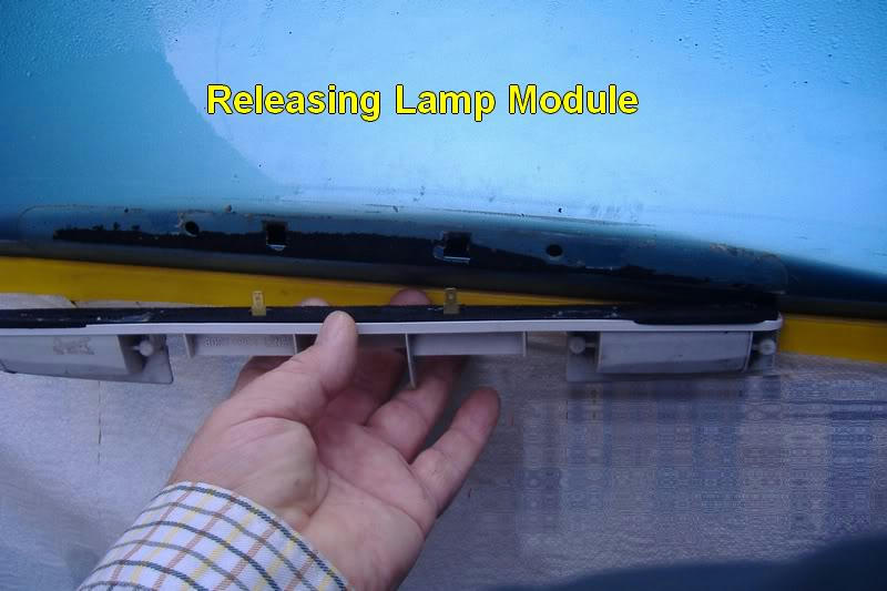
I'd read of people using a hair drier to soften the adhesive, but it soon became obvious that that
wasn't going to work. Maybe the freeze had something to do with it. Anyway, I decided to apply lots of white spirit to the foam while gently pulling the unit away from he lid. This sort of worked, but it really does need more brawn than brain. Eventually, it yielded to my will.
Image 13
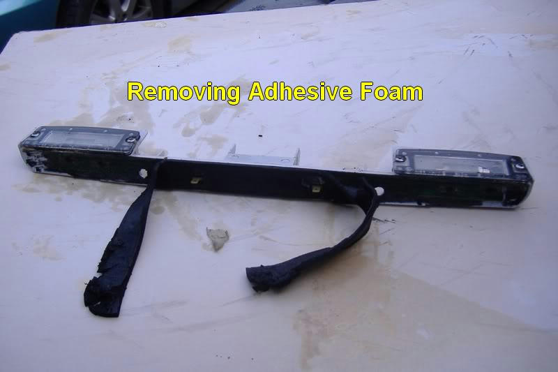
The adhesive foam was now a soggy mess and couldn't be reused (who'd want to?). I decided to strip away the foam and use something better (remember the double glazing stuff?). Under the foam is the printed circuit board that everyone talks about.
Image 14
With the help of an old toothbrush, more white spirit and old old pair of underpants, the black slop was eventually removed from the lamp. Here's what you get. Notice the cracked plastic - too much brawn I guess.
Image 15
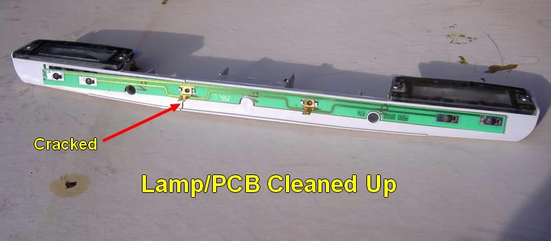
A dollop of Wilkinson's super glue soon fixed it. The PCB was unaffected. However, many people find that the tracks on this board are corroded so the lamps don't work. The two connecting lugs (feed and earth) are also a weak spot, because they're just rivetted on. Electrical tracks and connectors can be fixed using solder or simply replaced by rewiring the circuits. It's simple enough. Mine were in perfect nick, so I was left wondering why the LEDs went out.
It was at this point that I actually examined the LED bulbs. They simply flipped out of the clips! I suppose the constant slamming down of the lid had caused them to come out of the clips. Bad design?
Image 16
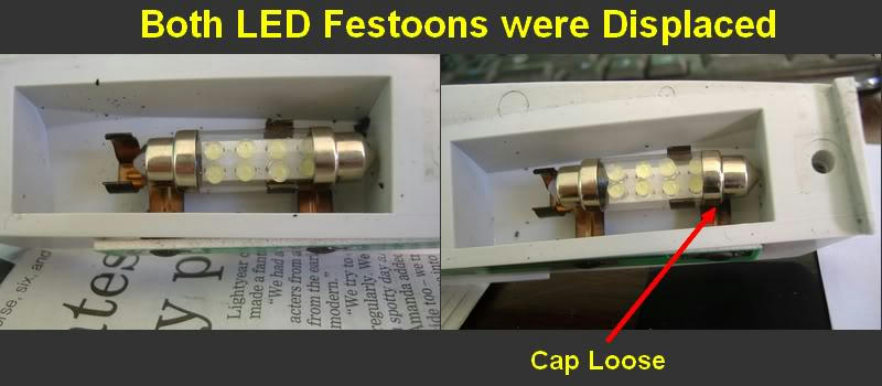
I took a closer look at them. When I took them out of the lamp, they more or less fell apart. The metal end caps were very slack and were used to nip onto the voltage resistors on each end. The body of the bulb is a plastic tube, not glass. Overall, a pretty cheap affair.
Image 17

Worse still, using a 12 volt supply (with correct polarity), they didn't work when I reassembled them. They'd blown/fused/popped or whatever LEDs do. They went in the bin. I found my trusty old festoons in the desk drawer (I never chuck anything away unless it's useless) and decided my LED lighting experience was now complete (long story).
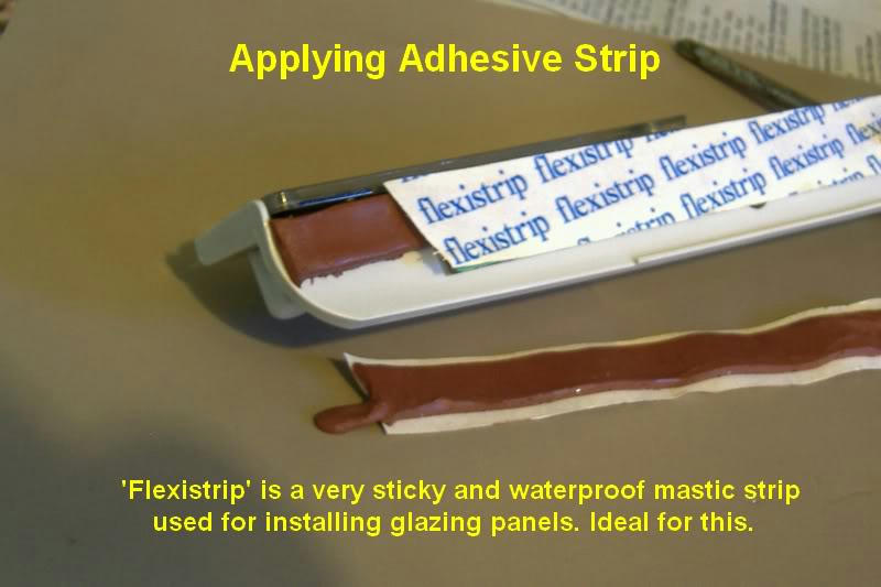
With the old bulbs back in place, I now decided to use the sticky mastic to reattach the lamp unit to the lid. The mastic comes in quarter-inch wide rolls with a peel-off backing. Two strips over the PBC would protect it from moisture and hold the unit in place. Here's the 'Flexistrip' mastic going on.
EDIT: If you want to use this sticking method rather than a double-sided foam strip, you need Butyl strip/tape available in various widths from eBay.
Image 18
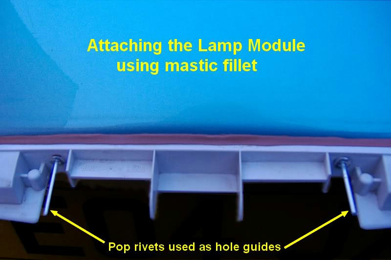
The lamp was then offered up to the lid, using a couple of pop rivets as locating pins. These go through the holes on the lid.
A small amount of pressure was applied to get complete adhesion. The lamp is actually held by the inner bolts on the plinth, so you just need to ensure the joint is waterproof. I put a thin fillet of mastic across the top edge to ensure this.
Image 19
You can now refit the spade connections and test the lamp.
My sheared plinth pin was fixed using super glue to locate it, then a reinforcing dollop of Plastic Padding.
The plinth goes back on in the reverse order. Before fitting, clean up the rubber seal around the periphery. It collects gunge. I decided to smear the upper seal with silicone sealant just to ensure a water-tight fit.The flange-nuts go on first using the stickum in the socket to prevent accidents. The screwits went on next. I advise being circumspect when fitting these. They will reslacken or shear the pin if overdone. I found that pressing on the plinth allows you to tighten the screwits without unduly stressing the pins. The rubber seal should be snug to the lid end to end.
Replace the lid liner by pressing in the fir tree cips.
Image 20
Stand back and give yourself a pat on the back.
Image 21

TC
Disclaimer:
You are responsible for any work or modifications carried out on your car and you undertake any such work at your own risk. The 75 and ZT Owners Club nor the original author of these How-To's can be held liable for anything that may happen as a result of you following these How-To's.
Any modifications should be reported to your insurance company.