Hi all,
I have had a few hours more out in the garage, and its time for an update:
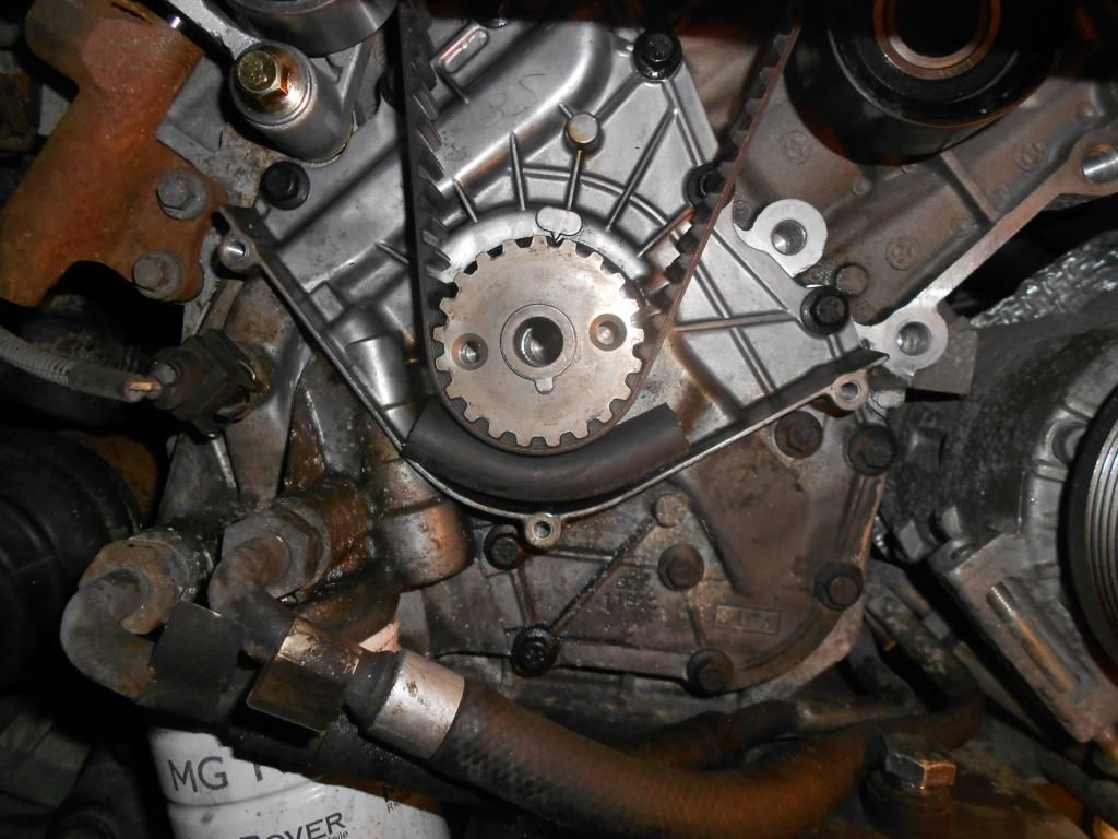
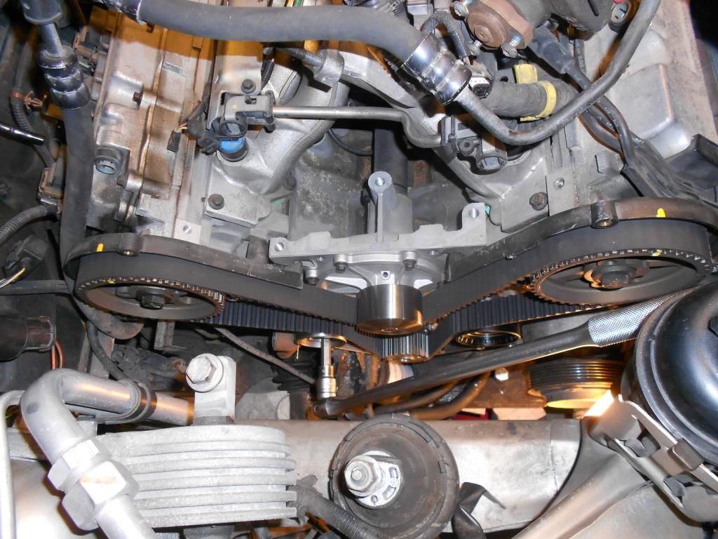
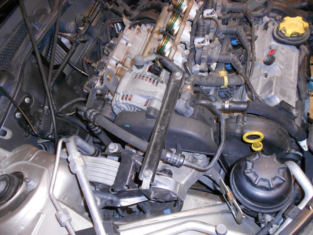
I continued from where I left the last session with removing the alternator, PAS pump and oil dipstick. Then loosen the oil cooler to gain access to the AC compressor bolts. I removed the two AC compressor bolts in the front, but left the rear one alone as I found it hard to reach. Then I removed the engine front plate and the front timing belt was then fully revealed:
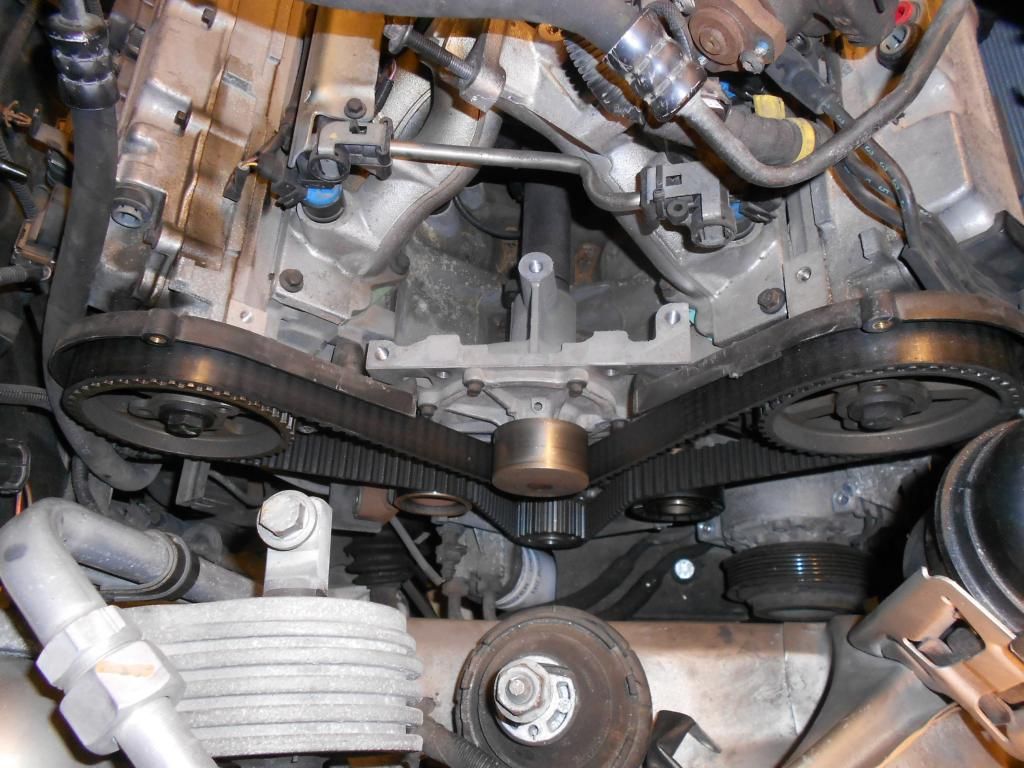
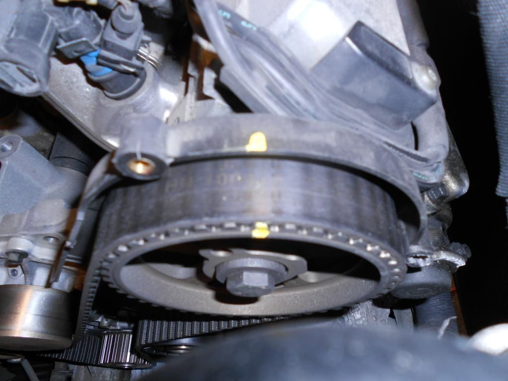
Then I made timing marks across the rear belt covers and their pulleys according to the haynes manual. I also checked that the engine was parked in the "safe position" while doing this:
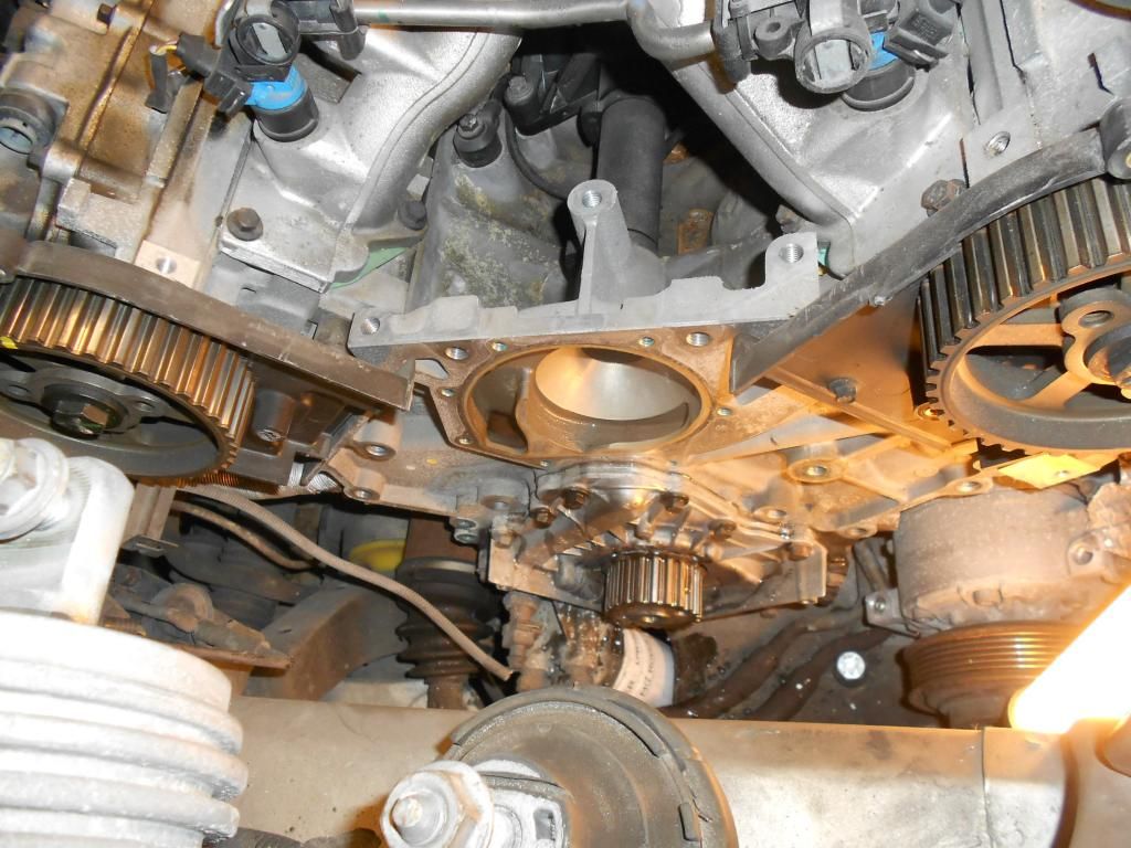
Cambelt + tensioner, tensioner pulley, idler pulley and water pump was then removed:
The cam pulleys did rotate slightly inwards when the cambelt was removed and needs to be rotated back into position when the new cambelt is fitted.
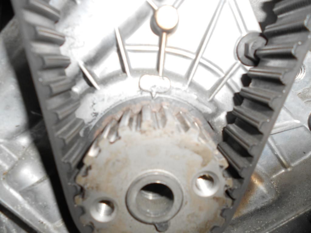
To my big surprise, I found a damaged area in the cambelt

:
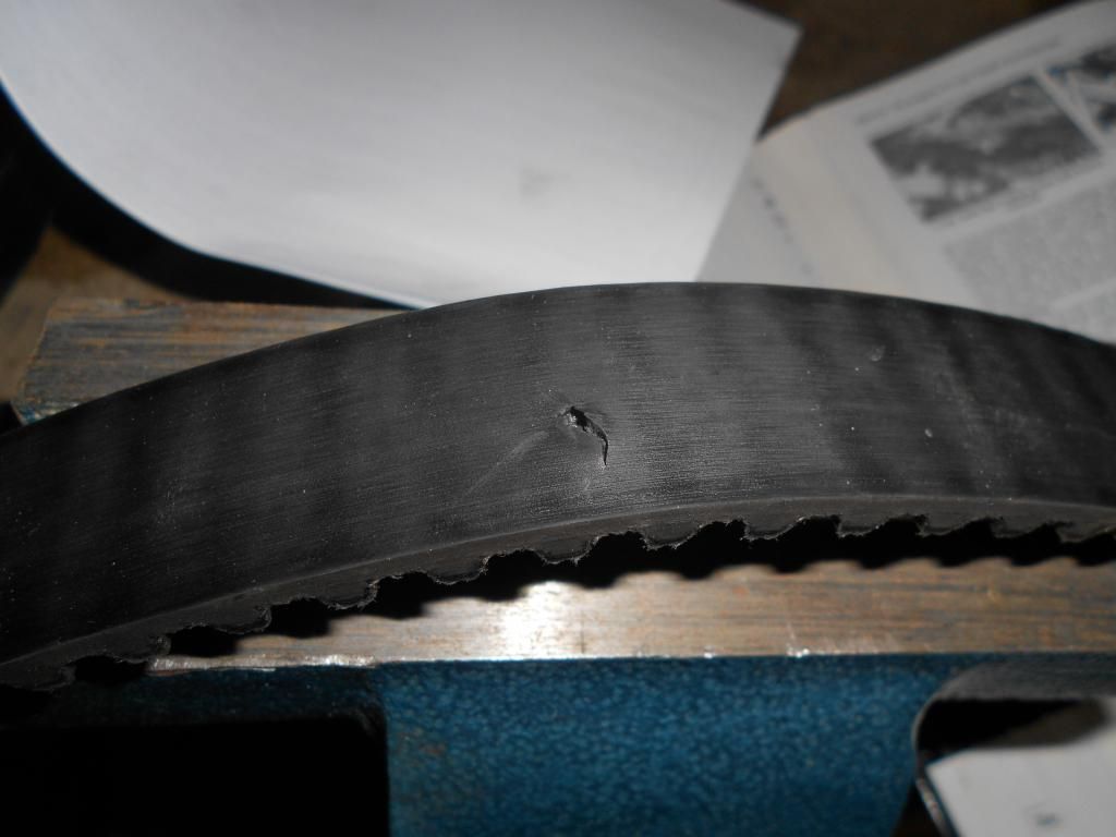
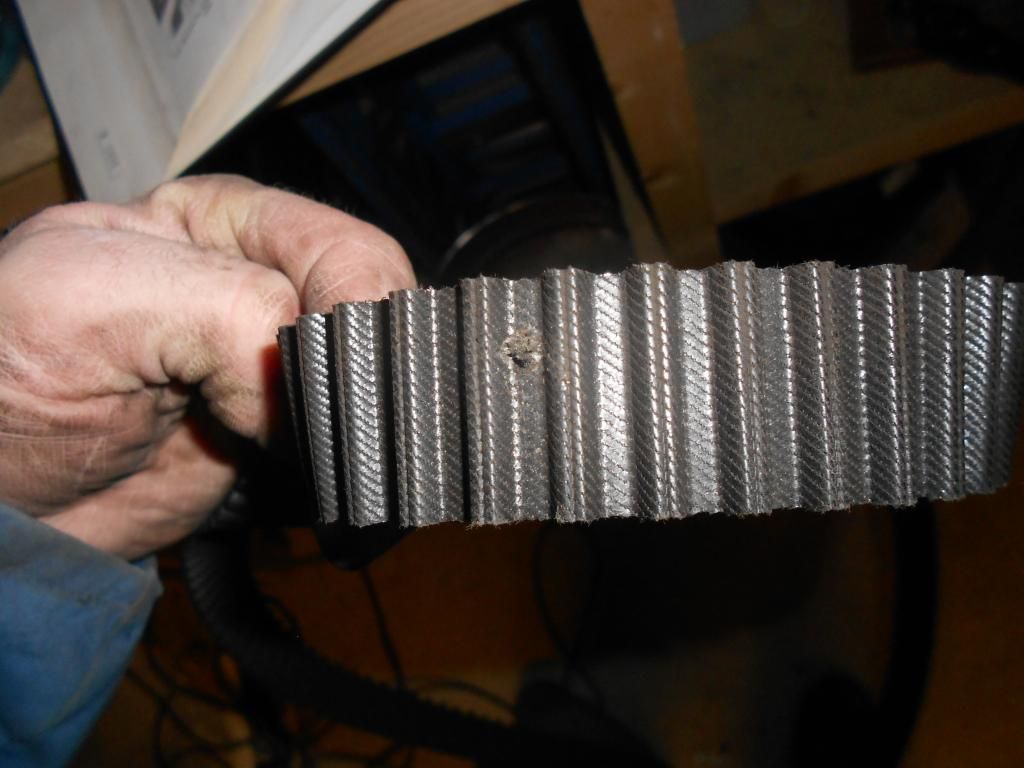
On closer inspection, I found a stone chip inside the damaged area. I also found some stone chips resting below the crankshaft pulley which has at some point found their way inside the cambelt covers.
Old and new waterpump:
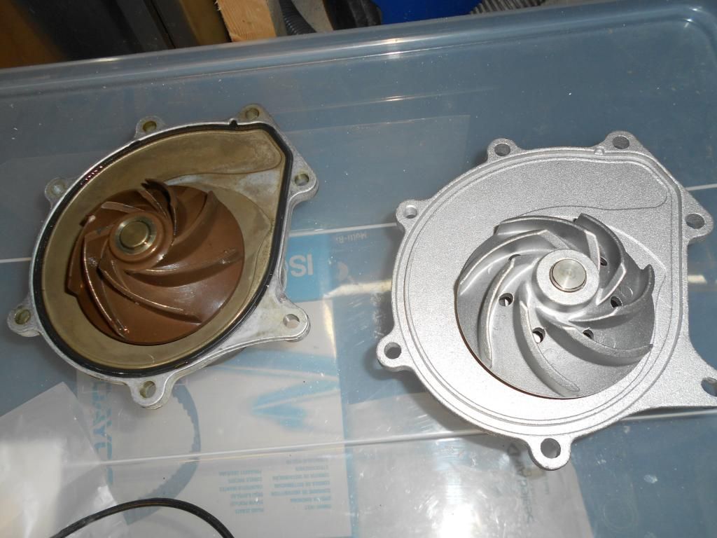
Old one has a plastic impeller, and the new one a metal one. The casting on the OEM pump is a level smoother than the replacement and that one has been in there since the car was new. Its casting was marked with a production date from -99.
The seal surface on the block was cleaned with some grit 400 wet-n-dry paper and wiped dry before the new pump was fitted together with a new seal to the block. I added a drop of loctite 243 to its bolts before mounting and torqued them up to 10Nm as specified.
The new idler pulley and tensioner pulled was mounted to the block. I also added a drop of loctite 243 to their threads prior to installation and torqued up their bolts to 45Nm as specified by the Haynes manual. The tensioner damper was compressed and locked in its initial position with a 1,5mm drill bit, as per the manual, now ready for installation. A new timing belt was put in place. I used a piece of rubber hose under the crankshaft pulley to keep it in place while routing the belt into position:
Starting at the cranckshaft puley the belt was routed around the idler pulley, then over the front inlet camshaft pulley which was held in the correct positon with a spanner, then around the water pump, then around the rear inlet camshaft pulley which was held in position with my sprocket tool and at last around the tensioner pulley. Tension was applied to the belt with the appropriate tooling in the hexagon slot in the tensioner pulley while installing the tensioner damper onto the block. Loctite 243 was added to the tensioner damper bolts prior to installation and torqued according to specifications:
 !!! AND NOW A WORD OF WARNING !!!
The tensioner pulley needs now to be adjusted and locked in position!!
This procedure is not described in either the haynes manual, the RAVE manual or the famous video on youtube!!
!!! AND NOW A WORD OF WARNING !!!
The tensioner pulley needs now to be adjusted and locked in position!!
This procedure is not described in either the haynes manual, the RAVE manual or the famous video on youtube!! I found this procedure in the enclosed document which came together with the new pulley. I was not aware of this procedure until I saw this document and would probably just fit the tensioner pulley "as-is". Many thanks to DMGRS Mat for this document

I have attached this document to this thread and will not go into more details about it here.
Another great thread explains this here:
http://forums.mg-rover.org/showthrea...32#post2934932
So basically, there may be some KV6 engines out there running with the adjustment bolt for the tensioner pulley only temporary fixed at 10 Nm and with the wrong adjustment!!!
I think that migth have been the case here also as I accidentially put my allen key into the adjustment fixing bolt in the tensioner pulley intead of the hexagon slot when turning the tensioner clockwise to release it from the tensioner damper. I am pretty sure I rotated the bolt some at that stage, confirming that the bolt was not properly made up!! Grrrr.... Bloddy LR garage that did the last TB change.... I will check that pulley bolt closer next time I am out in the garage!!
So then, before starting to put things back on and closing of the front end, the checklist should be as follows:
- Tripple check the timing marks.
- All bolts on water pump, pulleys and tensioner damper torqued to their specifed torque and loctite added to the specific threads.
- Tensioner pulley correctly adjusted and fixed with correct torque according to procedure. The lock pin in the tensioner damper shall be easily moved when the tension is correct.
- Lock pin removed from tensioner damper.
Then most things are reverse of removal. Its a good idea to fit a new AUX belt in the same operation and check its pulleys:
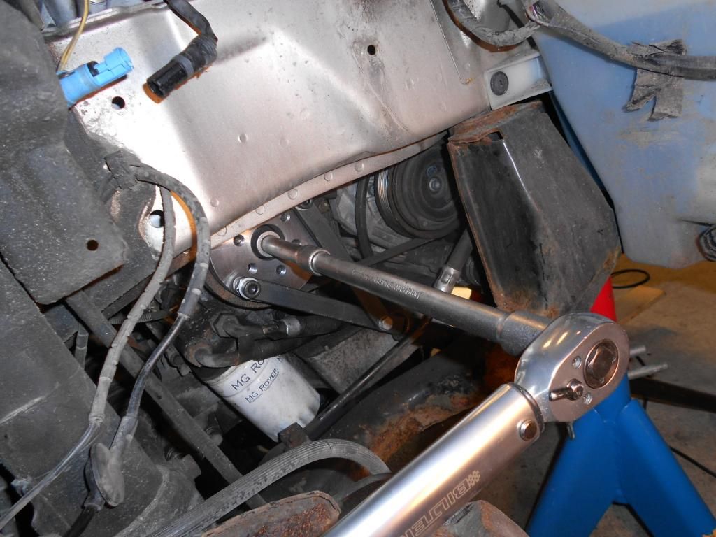
Remember to remove the crankshaft lock pin and tighten the crankshaft pulley to 160Nm using appropriate tooling:
So far, so good. I am very satisfied with the work done so far